Saltar al contenido principal

Lanzado en Septiembre 16, 2016. Modelos 1660, 1778. Disponible en GSM o CDMA / 32, 128, o 256 GB / Oro Rosa, Oro, Plata, Negro Mate y Negro Brillante.

Preguntas 1364 Ver todo

NO SIM Card bad soldering job

Hey guys, friend of mine brought me this phone without working sim (no sim message in the left top corner). Immidiately after openin, I've recognized something bad about the sim card reader, it’s full of connected solder.. any idea how to repair this stuff? I’have microscope and soldering and hot air station.

Block Image

Update (11/21/2019)

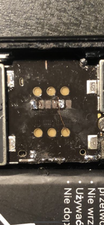
That’s what I’ve found underneath. Is there a possibility to repair those pads?

Block Image

Contestado! Ver respuesta Yo también tengo este problema

Es esta una buena pregunta?

Puntuación 0
Agregar un comentario

3 Respuestas

Solución Elegida

Arbaman may be correct about audio IC repair.

·         Clean the solder up so there are no bridges.

·          Check that (*#06#) brings up an IMEI number.

If it doesn’t, remove the logic board from the housing and check the audio IC, you will probably find it has been reflowed or repaired with jumper wires.

 If it has been worked on the most likely scenario is that they have put too much heat on the audio IC causing the solder balls under the baseband CPU to expand and bridge causing the “no sim and or searching no service.” This will require the baseband CPU to be removed and reballed, it is not an easy job.

If the repairer was not experienced they might have thought the sim tray was the problem.

If (*#06#) does bring up the IMEI number and there is no sign of audio IC repair go ahead and replace the sim reader.

Fue útil esta respuesta?

Puntuación 4

4 comentarios:

And repairing the pads under the sim reader?

- de

I cannot make out any damaged pads. I can only see one image with a lot of solder. Clean the solder up so there is no bridging and check you get an IMEI number and check audio ic. The sim reader may be the least of your problems.

- de

Even if all the pads are missing it is not that bigger job to run six jumpers. Just run them from J_DEBUG it is only a few millimetres away.

- de

I've updated the image of the broken pads. The jumper should come from where to where please?

- de

Agregar un comentario

If you are skilled enough and confidant enough then i would replace the sim reader, probably save you a lot of time than trying to make the bad one good

Fue útil esta respuesta?

Puntuación 1

4 comentarios:

I would try to repair this one, but it's obviously a problem of the soldering mess inside isnt it?

- de

@jrkstbl I agree with @danscreens , remove and replace, if there's already such a visible mess you can't rely on what's on the bottom. I wouldn't be surprised it's not the only damage on that board, especially if all started with an audio IC repair.

- de

Any possibility to rpair the pads? It shows up that the pads under are already tear of the logic board. I can see very small dost of copper probably, is it possible to solder a new material to them? Multiumeter showing nothing when i put a probe on it, buts is so tiny, i dont know if i can believe the multimeter.

- de

@jrkstbl Try to take and post a couple of pictures, so that we can see what you see. Agregar imágenes a una pregunta existente

- de

Agregar un comentario

Put more flux and re-solder with pencil bit iron.

Fue útil esta respuesta?

Puntuación 0
Agregar un comentario

Añadir tu respuesta

jrkstbl estará eternamente agradecido.
Ver Estadísticas:

Ultimas 24 horas: 0

Ultimos 7 días: 0

Ultimos 30 días: 2

Todo El Tiempo: 374