Introducción
Esta es solo una guía prerequisito para desconectar la mayoría de los conectores y remover la mayoría de los tornillos para sacar la placa madre. Las fotos están tomadas de manera tal que no puedes ver si el motor táptico está fuera o no.
Nota La placa lógica de cada iPhone y el sensor de huella digital ID Táctil están acoplados de fábrica, así que si reemplazas la placa lógica, inhabilitarás el ID Táctil "al menos que" también instales un botón de inicio de reemplazo que haya sido acoplado apropiadamente en la nueva placa lógica.
Abrir el iPhone 8 dañará los sellos herméticos en la pantalla. Si no reemplazas los sellos adhesivos, tu teléfono funcionará normalmente pero no será impermeable.
Qué necesitas
-
-
Usa el extremo plano de un spudger para hacer palanca y desconectar el conector de cable de cámara de su zócalo.
-
-
-
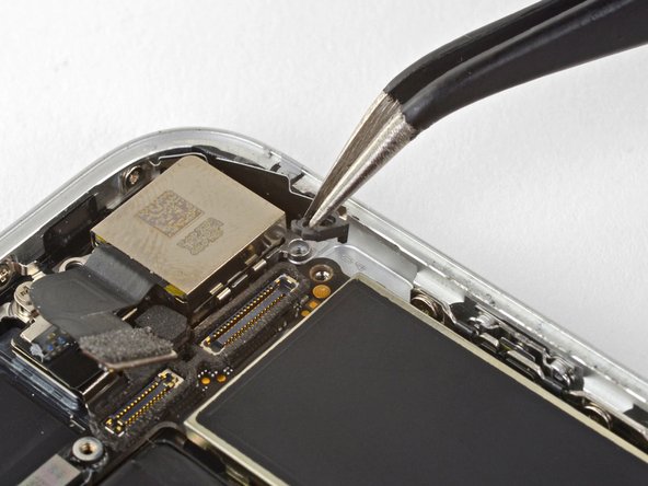
Remueve los dos tornillos que sujetan el soporte de la cámara trasera:
-
Un tornillo separador Phillips de 3.0 mm
-
Un tornillo Phillips de 3.1 mm
The screw and standoff are the other way round in this step. The photo shows the small screw removed and the standoff securing the logicboard is circled incorrectly. Also you may find that the standoff screw is not magnetic, making it a little tricky to replace!
Hi Michael,
You are correct; thanks for catching that! The original image was correct, and for some reason the image was updated, and no longer correct. I have reverted it back to the original image.
These screws are not magnetized! If you are trying to put them back, use some tweezers to align them, and while still using the tweezers, grab your standoff driver and push down, then you can screw it in with ease.
Thanks for the tip.
Habel -
-
-
-
Remueve los dos tornillos que sujetan el soporte de cable superior:
-
Un tornillo Phillips de 2.9 mm
-
Un tornillo Phillips de 1.3 mm
Logically - one wouldn’t need to take out all these things to take out something at the bottom of the phone - but in order to get good access to it, you must remove the logic board - which is long and all the way up at the top connected to the antenna. Follow the steps - it works.
-
-
-
-
Remueve los tres tornillos de Phillips de 1.3 mm que sujetan el componente de antena superior izquierda
-
-
-
Remueve el tornillo de 1.4 mm que sujeta el componente de la antena al borde superior de la caja.
Be careful not to strip this screw...I did and I'm going to try to proceed without taking off the antenna component.
Update: You can still go on with the replacement if you do not take off the antenna component
I think this screw is stripped on my iPhone , shittt. So I can just skip this part? or what?
If you can avoid putting in battery after this screw, that’ll be easier. I wound up using bit only with my fingers to get an initial thread going.
-
-
-
Remueve el componente de antena.
-
-
-
Remueve los dos tornillos que sujetan el clip de toma a tierra en el borde superior izquierdo de la placa lógica:
-
Un tornillo Phillips de 1.5 mm
-
Un tornillo Phillips de 2.6 mm
-
-
-
Remueve el clip de toma a tierra.
what happen if don't put this part?
Hi Albert,
It’s hard to tell. Most phone functions will probably work, but you may start getting quirky problems.
If it comes out it must go back in *no spare parts *
J'aurais plutôt dit "...le câble de mise à la masse"
Bonjour @roroancet, merci beaucoup de votre remarque ! Cela nous a donné l'occasion de plonger dans l'univers de l'électricité ! Il s'avère ainsi que la mise à la masse est le terme approprié ici. J'ai corrigé notre erreur. La prochaine fois, n'hésitez pas à le faire vous-même. iFixit est un wiki modifiable par tout le monde. Encore merci pour votre attention !
-
-
-
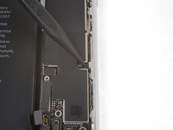
Remueve los tres tornillos que sujetan la placa madre:
-
Un tornillo Phillips de 1.8 mm
-
Un tornillo separador de 2.5 mm
-
Un tornillo separador de 2.2 mm
The One 1.8 mm Phillips screw was buried under some gasket material. It took some twezzer work to get that material off.
this is probably the most difficult part because the ‘top 2.5 mm on my version was under a piece of ribbon cable that had to be pulled back. Also notice - this picture is inverted. So the locations are reversed (obviously for clarity)
Buried 1.8mm Phillips easily located under the gasket material by zooming in on the photo to see position relative to connectors. Material is fibrous, so be patient.
I’ve been searching on internet about the black stickers on those parts in the phone and I found nothing about them, what are they? Electrical Tapes? Does it make any differences if we remove them? If yes is, there anything else we can use to replace them? We’re they are for any specific purposes? Thanks in advance if anyone can help me understand
-


Para volver a ensamblar tu dispositivo, sigue los pasos mencionados arriba en orden inverso.
Lleva tus residuos electrónicos a un centro de reciclaje electrónico.
¿La reparación no salió como planeabas? Fíjate en nuestra comunidad de Respuestas para ayuda de resolución de problemas.
Para volver a ensamblar tu dispositivo, sigue los pasos mencionados arriba en orden inverso.
Lleva tus residuos electrónicos a un centro de reciclaje electrónico.
¿La reparación no salió como planeabas? Fíjate en nuestra comunidad de Respuestas para ayuda de resolución de problemas.
Un agradecimiento especial a estos traductores:
100%


Estos traductores nos están ayudando a reparar el mundo! ¿Quieres contribuir?
Empezar a traducir ›


When replacing, used iFixit tweezers to gently hold/bend the cable, and used my finger to press the connector back in place. This was the best way I could get the connector lined up and seated properly.
Habel - Contestar