Esta versión puede contener ediciones incorrectas. Cambie a la última instantánea verificada.
Introducción
Error
Example:
[video|http://vimeo.com/1234] or [video|http://vimeo.com/1234]Optional Caption[/video]
Current text:
[video | http: //www.youtube.com/watch? v = BnGZy74xMOY]
Esta guía le mostrará cómo reemplazar el panel frontal de su iPad Wi-Fi.
Qué necesitas
-
-
Si está agrietado el cristal de la pantalla, mantenga aún más la rotura contenida y prevenir daños físicos durante su reparación con cinta adhesiva el vidrio.
-
Coloque tiras de cinta adhesiva transparente sobre la pantalla del iPad se solapan hasta que toda la superficie está cubierta.
-
Haga todo lo posible para seguir el resto de la guía como se ha descrito. Sin embargo, una vez que el vidrio se rompe, es probable que continúe a agrietarse a medida que trabaja, y es posible que necesite usar una herramienta de palanca de metal para recoger el vaso.
-
-
Este paso está sin traducir. Ayuda a traducirlo
-
There are 14 metal clips holding the display assembly in place, shown at left. As you pry in the following steps, do your best to pry around these clips and not slice through them with your opening tool.
-
-
Este paso está sin traducir. Ayuda a traducirlo
-
Insert a metal spudger between the top edge of the display assembly and the rear panel assembly.
-
Rotate the spudger away from you to release the tabs along the top edge of the display.
-
Insert a second metal spudger between the top edge of the display assembly and the rear panel assembly to keep the tabs from snapping back into place.
-
-
Este paso está sin traducir. Ayuda a traducirlo
-
With one spudger, work your way along the right edge of the iPad.
-
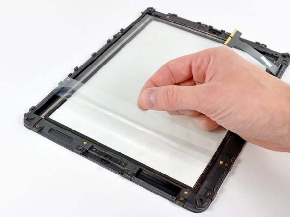
The front panel is held to the aluminum back by metal clips on the top, bottom, and left sides. The right side has plastic tabs which slide into recesses in the backplate.
-
Once the clips are released, lift the left side of the front panel up and slide it to the left to clear the tabs from the aluminum backplate.
-
-
Este paso está sin traducir. Ayuda a traducirlo
-
Lift the display assembly away from the rear panel assembly by its bottom edge.
-
-
Este paso está sin traducir. Ayuda a traducirlo
-
In the following steps, you will disconnect the three cables attaching the display assembly to the logic board. The cables are for the following components:
-
Digitizer
-
Ambient Light Sensor
-
Display Data Cable
-
-
Este paso está sin traducir. Ayuda a traducirlo
-
Use the edge of a plastic opening tool to flip up the retaining flaps holding the digitizer ribbon cables in their sockets on the logic board.
-
Pull the digitizer ribbon cables straight out of their sockets.
-
-
Este paso está sin traducir. Ayuda a traducirlo
-
Use a plastic opening tool to remove the ambient light sensor connector from its socket by gently prying upward.
-
-
-
Este paso está sin traducir. Ayuda a traducirlo
-
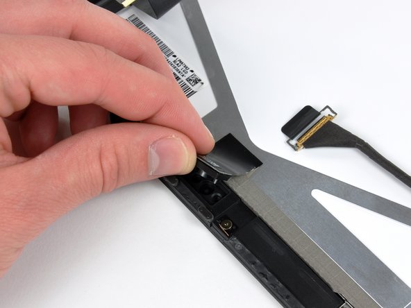
Disconnect the display data cable from the main board by flipping up the metal retainer by its black plastic pull tab.
-
Pull the cable connector away from its socket.
-
-
Este paso está sin traducir. Ayuda a traducirlo
-
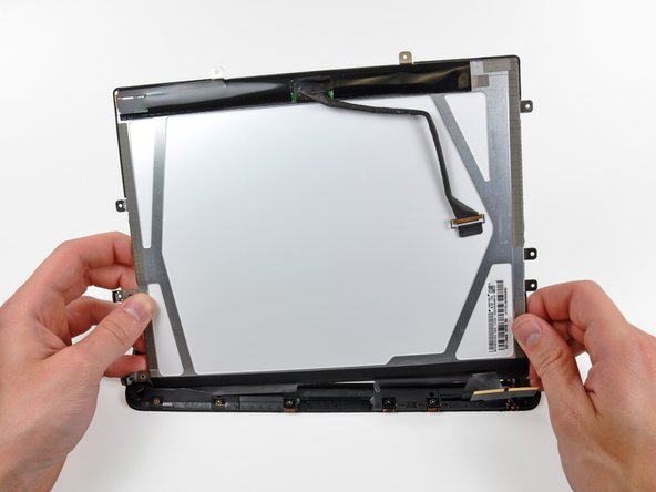
Remove the display assembly from the rear panel assembly.
-
-
-
Utilice el borde de una herramienta de apertura de plástico para hacer palanca con cuidado la placa del sensor de luz ambiental del adhesivo que lo sujeta al marco de la pantalla.
-
Una vez que haya ganado espacio suficiente, retire el sensor de luz ambiental de la pantalla LCD.
-
-
Este paso está sin traducir. Ayuda a traducirlo
-
While holding the digitizer cable down, carefully peel back the piece of tape connecting the digitizer cable to the display frame.
-
-
Este paso está sin traducir. Ayuda a traducirlo
-
Remove the three T5 Torx screws securing the clips and LCD brackets covered in EMI tape near the home button switch.
-
Carefully peel the display clip and its attached tape off the black plastic display frame.
-
-
Este paso está sin traducir. Ayuda a traducirlo
-
Remove the remaining T5 Torx screws securing the LCD to the black plastic display frame.
-
-
Este paso está sin traducir. Ayuda a traducirlo
-
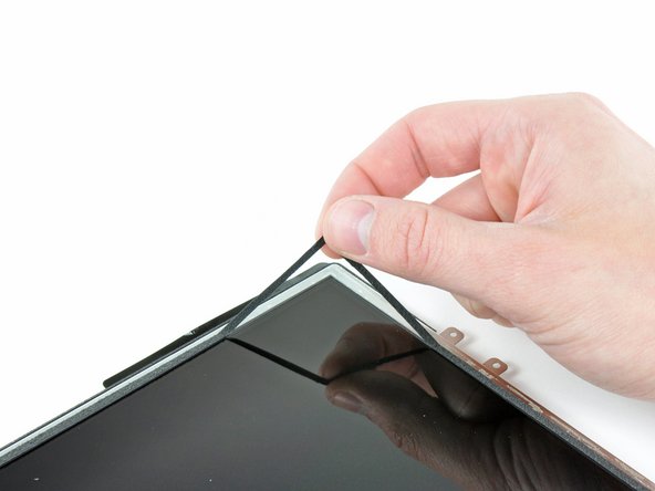
Insert the edge of a plastic opening tool under one of the ears attached to the steel LCD frame.
-
Twist the plastic opening tool to gently pry the LCD up off the adhesive securing it to the front glass panel.
-
-
Este paso está sin traducir. Ayuda a traducirlo
-
Repeat the process detailed on the previous step to pry up the display around the three sides opposite the digitizer cable side of the display.
-
-
Este paso está sin traducir. Ayuda a traducirlo
-
Lift the LCD from its free end, and remove it from the display frame.
-
Carefully peel the adhesive securing the long side of the LCD to the display frame, then remove the LCD.
-
-
Este paso está sin traducir. Ayuda a traducirlo
-
If it is still stuck to the front panel, remove the strip of EMI tape near the ambient light sensor socket.
-
-
Este paso está sin traducir. Ayuda a traducirlo
-
If they are still in good shape, transfer the clips and EMI tape near the bottom of the LCD to your new LCD.
-
-
-
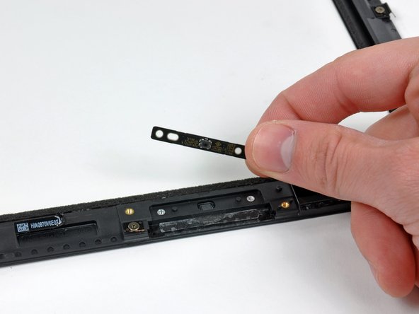
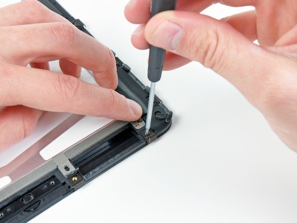
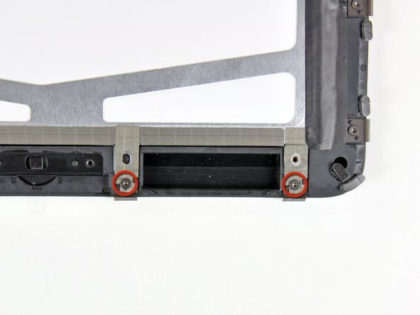
Retire los dos tornillos T5 Torx que sujetan el interruptor del botón de inicio al marco de la pantalla de plástico.
-
Retire la placa de interruptor del botón de inicio del conjunto del panel frontal.
-


Continúe con la instalación siguiendo la guía de Paso 12 en reversa .
Continúe con la instalación siguiendo la guía de Paso 12 en reversa .
Cancelar: No complete esta guía.
44 personas más completaron esta guía.
Un agradecimiento especial a estos traductores:
100%

¡ irlanda nos está ayudando a reparar el mundo! ¿Quieres contribuir?
Empezar a traducir ›

Un comentario
LCD cable is easily trapped under lcd on reassembly without due care causing colour differences on snapping into place