Esta versión puede contener ediciones incorrectas. Cambie a la última instantánea verificada.
Qué necesitas
-
Este paso está sin traducir. Ayuda a traducirlo
-
Peel back and remove the adhesive tape covering the headphone jack assembly.
-
-
Este paso está sin traducir. Ayuda a traducirlo
-
Remove the single 2.6 mm Phillips #0 screw securing the camera cable to the headphone jack assembly.
-
-
Este paso está sin traducir. Ayuda a traducirlo
-
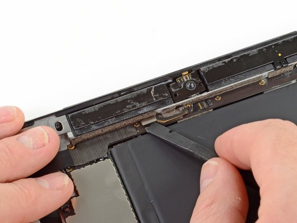
Using the flat end of a spudger, pry the front-facing camera off of its socket on the headphone jack assembly.
-
Without removing the spudger, slide the spudger to the right, releasing the adhesive holding down the camera cable.
-
-
-
Este paso está sin traducir. Ayuda a traducirlo
-
Using the tip of the spudger, flip up the retaining flap on the microphone cable ZIF connector.
-
Insert the tip of the spudger underneath the microphone ribbon cable, removing it from its ZIF connector.
-
Slide the spudger to the left, releasing the adhesive holding the microphone ribbon cable to the headphone jack assembly.
-
-
Este paso está sin traducir. Ayuda a traducirlo
-
Use the flat end of the spudger to pry up the antenna connector cable out of its socket on the headphone jack assembly board.
-
-
Este paso está sin traducir. Ayuda a traducirlo
-
Flip up the retaining flap securing the volume/power button ribbon cable connector to the headphone jack assembly board.
-
Remove the volume button ribbon cable from its ZIF connector.
-
-
Este paso está sin traducir. Ayuda a traducirlo
-
Remove the following screws from the headphone jack assembly:
-
Five 2.6 mm Phillips #0
-
Two 2.2 mm Wide Head Phillips #00
-
Two 2.6 mm Phillips #00
-
-
Este paso está sin traducir. Ayuda a traducirlo
-
Holding onto the ribbon cable of the headphone jack assembly, carefully pull the assembly parallel to the iPad, toward the bottom of the device.
-
-
Este paso está sin traducir. Ayuda a traducirlo
-
Grasping the headphone jack assembly with both hands, pull the assembly from the iPad, minding any cables that may get caught.
-