Saltar al contenido principal

Esta versión puede contener ediciones incorrectas. Cambiar a la última instantánea verificada.

Qué necesitas

  1. Este paso está sin traducir. Ayuda a traducirlo

    : paso 1, imagen 1 de 2 : paso 1, imagen 2 de 2
    • Loosen the three Phillips screws securing the access door to the bottom edge of your iMac.

    • These screws will remain captive in the access door.

    • Remove the access door from your iMac.

    • During reassembly, fasten the access door loosely and align it with the pocket cut into the outer case of the iMac before fully tightening the screws.

  2. , Panel de Vidrio: paso 2, imagen 1 de 2 , Panel de Vidrio: paso 2, imagen 2 de 2
    • Antes de empezar, desconecte su iMac y recuestela sobre una superficie suave.

    • Adhiera una ventosa en los 2 angulos superiores del panel de vidrio.

    • Para pegar las ventosas primero posicione sus manijas paralelas al borde del panel de vidrio. Presione suavemente las ventosas contra el vidrio y gire las manijas de vacio hacia el panel de vidrio.

    • Si sus ventosas no se pegan, limpie la superficie del vidrio y la goma de sus ventosas con un solvente liviano.

    • Insertar traducción aquí

    • Insertar traducción aquí

  3. : paso 3, imagen 1 de 2 : paso 3, imagen 2 de 2
    • Tire despacio el panel de vidrio perpendicular a la cara del LCD con cuidado ya que hay pestañas de metal en la parte inferior del panel de vidrio.

    • Remueva el panel de vidrio hacia arriba sacando cuidadosamente las pestañas de acero y coloque sobre una superficie limpia.

    • Durante la reinstalación, asegurese que la cara interior del panel de vidrio esta perfectamente limpia y que no haya quedado suciedad ni impresiones de dedos sobre el LCD ya que seria visibles al encender el iMac.

  4. , Pantalla: paso 4, imagen 1 de 3 , Pantalla: paso 4, imagen 2 de 3 , Pantalla: paso 4, imagen 3 de 3
    • Retira los ocho tornillos Torx T10 de 8 mm que sujetan la pantalla a la carcasa exterior.

    • Las dos últimas imágenes son tomas detalladas de cada lado de la pantalla.

  5. : paso 5, imagen 1 de 1
    • Levanta ligeramente el borde superior de la pantalla para sacarlo de la carcasa exterior.

    • No lo levantes demasiado. Hay varios cables que conectan la pantalla a la placa lógica.

  6. : paso 6, imagen 1 de 3 : paso 6, imagen 2 de 3 : paso 6, imagen 3 de 3
    • Saca el cable plano de sincronización vertical de su zócalo en la placa del controlador LED cerca de la esquina superior izquierda de tu iMac.

    • El cable plano de sincronización vertical tiene un extremo de estilo ZIF, pero el zócalo no tiene bloqueo ni solapa de retención. Simplemente saca el cable de su zócalo hacia el lado de la unidad óptica del iMac para desconectarlo de la placa del controlador LED.

  7. : paso 7, imagen 1 de 3 : paso 7, imagen 2 de 3 : paso 7, imagen 3 de 3
    • Gira la pantalla fuera de la carcasa exterior lo suficiente para desconectar el cable de alimentación de la retroiluminación LED de la placa del controlador LED.

    • Desconecta el cable de alimentación de la retroiluminación LED presionando el mecanismo de bloqueo mientras tiras del conector para sacarlo de su zócalo (hacia el borde inferior del iMac).

  8. : paso 8, imagen 1 de 1
    • Aprieta los dos brazos del conector del cable de datos de la pantalla para desbloquearlo de su zócalo en la placa lógica.

    • Saca el conector del cable de datos de la pantalla de su zócalo en la placa lógica.

    • Ten cuidado al desconectar y volver a conectar este cable, ya que se daña fácilmente.

  9. : paso 9, imagen 1 de 1
    • Desconecta el conector del cable del sensor térmico LCD de su zócalo en la placa lógica.

    • Si tu ventilador gira a toda velocidad después de completarse, verifica esta conexión o el cable del sensor térmico del disco duro.

  10. : paso 10, imagen 1 de 1
    • Tira con cuidado de la pantalla hacia el borde superior de tu iMac y sácala de la carcasa exterior, prestando atención a los cables que puedan quedar atrapados.

  11. Este paso está sin traducir. Ayuda a traducirlo

    : paso 11, imagen 1 de 1
    • Remove the following four screws securing the power supply to the outer case:

    • Two 22.2 mm fine-thread T10 Torx

    • One 25 mm coarse-thread T10 Torx

    • One 9 mm coarse-thread T10 Torx

    • The next few steps bring your hands close to the exposed face of the power supply. To avoid a high voltage shock from the many large capacitors attached to the board, do not touch the face of the power supply.

  12. Este paso está sin traducir. Ayuda a traducirlo

    : paso 12, imagen 1 de 1
    • Carefully lift the power supply out of the outer case and rotate it to expose the cable lock as shown, minding the DC-Out cable still attaching it to the iMac.

    • Disconnect the DC-In cable by depressing the locking mechanism on the connector while you pull the connector away from its socket on the power supply.

    • Once the locking mechanism has cleared the socket, pull the DC-In connector away from the power supply.

  13. Este paso está sin traducir. Ayuda a traducirlo

    : paso 13, imagen 1 de 1
    • Disconnect the AC-In cable by depressing the locking mechanism while pulling the connector away from its socket.

    • Remove the power supply from the outer case.

  14. , Unidad Óptica: paso 14, imagen 1 de 1
    • Saca el conector del sensor térmico de la unidad óptica directamente de su zócalo en la placa lógica.

  15. : paso 15, imagen 1 de 1
    • Retira los cuatro tornillos Torx T10 de 9 mm que sujetan la unidad óptica a la carcasa exterior.

  16. : paso 16, imagen 1 de 1
    • Levanta el borde interior de la unidad óptica y maniobra su conector más allá del marco conectado a la placa lógica.

    • Retira con cuidado la unidad óptica de sus clavijas de montaje en el borde de la carcasa exterior para tener espacio para desconectar el cable de la unidad óptica.

  17. : paso 17, imagen 1 de 1
    • Usa el extremo plano de un spudger para ayudar a desconectar el cable de la unidad óptica.

  18. Este paso está sin traducir. Ayuda a traducirlo

    : paso 18, imagen 1 de 1
    • Remove the single 13 mm T10 Torx screw securing the optical drive fan to the outer case.

  19. Este paso está sin traducir. Ayuda a traducirlo

    : paso 19, imagen 1 de 1
    • Pull the optical drive off the pins attached to the outer case.

  20. Este paso está sin traducir. Ayuda a traducirlo

    : paso 20, imagen 1 de 1
    • Pull the optical drive fan connector away from its socket on the logic board.

    • Remove the optical drive fan from the iMac.

  21. Este paso está sin traducir. Ayuda a traducirlo

    : paso 21, imagen 1 de 1
    • Pull the left and right speaker connectors toward the right side of the iMac to disconnect them from the logic board.

  22. Este paso está sin traducir. Ayuda a traducirlo

    : paso 22, imagen 1 de 1
    • Disconnect the audio port cable by pulling its connector toward the right side of the iMac.

  23. Este paso está sin traducir. Ayuda a traducirlo

    : paso 23, imagen 1 de 1
    • Disconnect the AirPort cable by lifting its connector off the socket on the logic board.

    • Lift the connector perpendicular to the face of the logic board.

  24. Este paso está sin traducir. Ayuda a traducirlo

    : paso 24, imagen 1 de 1
    • Disconnect the following cables by pulling their connectors toward the top edge of the iMac:

    • Camera cable

    • Hard drive thermal sensor

    • Hard drive fan

    • Microphone

    • Disconnect the following cables by pulling their connectors toward the right edge of the iMac:

    • Ambient temperature sensor

    • Bluetooth cable

  25. Este paso está sin traducir. Ayuda a traducirlo

    : paso 25, imagen 1 de 1
    • Disconnect the CPU fan and power button by pulling their connectors toward the left edge of the iMac.

  26. Este paso está sin traducir. Ayuda a traducirlo

    : paso 26, imagen 1 de 2 : paso 26, imagen 2 de 2
    • If present, remove the piece of tape covering the IR sensor connector.

    • Disconnect the IR sensor by pulling its connector toward the top edge of the iMac.

  27. Este paso está sin traducir. Ayuda a traducirlo

    : paso 27, imagen 1 de 1
    • Use your fingers to lift IR sensor assembly straight up out of the outer case.

  28. Este paso está sin traducir. Ayuda a traducirlo

    : paso 28, imagen 1 de 1
    • Remove the following six screws securing the logic board to the outer case:

    • Three 25 mm T10 Torx

    • Two 21.5 mm T10 Torx

    • One 7 mm T10 Torx

  29. Este paso está sin traducir. Ayuda a traducirlo

    : paso 29, imagen 1 de 2 : paso 29, imagen 2 de 2
    • Remove the plastic ducts from the side of the LED driver board and the hard drive by pulling them away from the outer case.

  30. Este paso está sin traducir. Ayuda a traducirlo

    : paso 30, imagen 1 de 1
    • Carefully remove the aluminum tape attaching the GPU heat sink to the outer case.

    • It is not necessary to completely remove the aluminum tape from the GPU heat sink.

  31. Este paso está sin traducir. Ayuda a traducirlo

    : paso 31, imagen 1 de 1
    • In the following steps, you will maneuver the logic board out from the outer case. In doing so, be aware of the many cables still attaching the logic board to the outer case.

    • Be sure the logic board clears the plastic lower optical drive fan mounting pin before lifting it up, as it is easily snapped off.

  32. Este paso está sin traducir. Ayuda a traducirlo

    : paso 32, imagen 1 de 1
    • Carefully pull the logic board slightly away from the outer case.

    • While holding the board away from the outer case, rotate the board back and forth while lifting up to release it from the outer case.

  33. Este paso está sin traducir. Ayuda a traducirlo

    : paso 33, imagen 1 de 2 : paso 33, imagen 2 de 2
    • Now that the lower edge of the board is free from the outer case, rotate the logic board toward yourself to expose its rear face.

    • The following connector has a tendency to stick in its socket. If so, insert a metal spudger into the gap between the connecter and its socket. Twist the spudger to separate the two components.

    • Carefully pull the optical drive connector away from its socket on the logic board.

    • Pull the connector perpendicular to the face of the logic board.

  34. Este paso está sin traducir. Ayuda a traducirlo

    : paso 34, imagen 1 de 1
    • Disconnect the DC-In cable from the logic board by simultaneously depressing the locking lever on the connector while pulling it away from its socket.

    • Remove the logic board from the outer case.

    • During reassembly of the logic board, pay attention to the position of the I/O connectors. When the board is back in the case, insert a USB or Thunderbolt cable into one of the connectors to align it perfectly.

  35. Este paso está sin traducir. Ayuda a traducirlo

    : paso 35, imagen 1 de 1
    • If present, remove the pieces of clear tape securing the ambient temperature sensor cable and the left speaker cable to the rear case.

  36. Este paso está sin traducir. Ayuda a traducirlo

    : paso 36, imagen 1 de 1
    • Remove the two 13 mm T10 Torx screws securing the CPU fan to the outer case.

  37. Este paso está sin traducir. Ayuda a traducirlo

    : paso 37, imagen 1 de 1
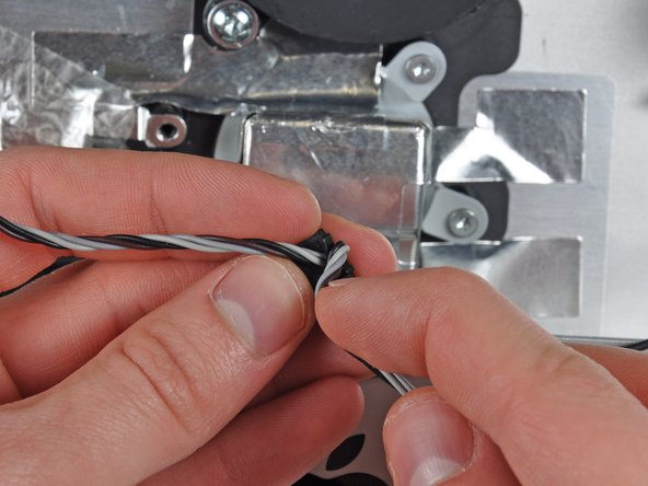
    • Peel the cable retainer off the side of the CPU fan.

    • If the tape on the cable retainer loses adhesion, remove the existing foam tape and either use double-sided tape or glue to reattach it to the CPU fan.

    • Remove the CPU fan from the outer case, minding any cables that may get caught.

  38. Este paso está sin traducir. Ayuda a traducirlo

    : paso 38, imagen 1 de 1
    • De-route the left speaker cable from the clips securing it to the outer case.

  39. Este paso está sin traducir. Ayuda a traducirlo

    : paso 39, imagen 1 de 2 : paso 39, imagen 2 de 2
    • Carefully remove the left speaker and ambient temperature sensor cables from the CPU fan cable retainer.

  40. Este paso está sin traducir. Ayuda a traducirlo

    : paso 40, imagen 1 de 2 : paso 40, imagen 2 de 2
    • Use the flat end of a spudger to pry open the ambient temperature sensor retainer.

    • Remove the ambient temperature sensor from the CPU fan.

    • If your new CPU fan does not have the ambient temperature sensor retainer attached, transfer it from your old fan to the new one.

Linea de Meta

12 personas más completaron esta guía.

0 comentarios

Agregar Comentario

Ver Estadísticas:

Ultimas 24 horas: 2

Ultimos 7 días: 7

Ultimos 30 días: 26

Todo El Tiempo: 41,620