Esta versión puede contener ediciones incorrectas. Cambie a la última instantánea verificada.
Qué necesitas
-
Este paso está sin traducir. Ayuda a traducirlo
-
Lay your iBook upside down on a flat surface.
-
Use a coin to rotate the battery locking screw 90 degrees clockwise.
-
Lift the battery out of the computer.
-
-
Este paso está sin traducir. Ayuda a traducirlo
-
Pull the keyboard release tabs toward you and lift up on the keyboard until it pops free.
-
Flip the keyboard over, away from the screen, and rest it face-down on the trackpad area.
-
-
Este paso está sin traducir. Ayuda a traducirlo
-
Remove the four silver Phillips screws that secure the RAM shield.
-
-
Este paso está sin traducir. Ayuda a traducirlo
-
Pull the keyboard cable up from the logic board, holding the cable as close to the connector as possible.
-
-
Este paso está sin traducir. Ayuda a traducirlo
-
Use a spudger or small flathead screwdriver to remove the three rubber feet from the lower case.
-
-
Este paso está sin traducir. Ayuda a traducirlo
-
Use a spudger or small flathead screwdriver to pry up the three metal rings that housed the rubber bumpers.
-
-
Este paso está sin traducir. Ayuda a traducirlo
-
Remove the three Torx screws using a T8 Torx screwdriver.
-
-
Este paso está sin traducir. Ayuda a traducirlo
-
Remove the two 4.5 mm Phillips screws on either sides of the battery contacts.
-
-
Este paso está sin traducir. Ayuda a traducirlo
-
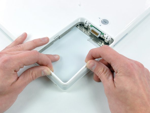
Push the thin rims of the lower case surrounding the battery compartment in, bending them past the tabs, and then lift up to free that corner of the lower case.
-
-
Este paso está sin traducir. Ayuda a traducirlo
-
There is a slot on the wall of the battery compartment that locks the lower case in place. Use a small flathead screwdriver to pry out the slot's lower rim and pull up on the lower case to free the slot from the tabs holding it.
-
-
Este paso está sin traducir. Ayuda a traducirlo
-
Run a spudger along the seam between the lower case and upper case on the front of the computer to free the tabs locking the lower case. Pull up on the lower case and continue to use the spudger as necessary until you hear three distinct clicks.
-
-
Este paso está sin traducir. Ayuda a traducirlo
-
Continue to run the spudger around the front right corner. There are two tabs on the port side of the computer, one near the front corner and one near the sound-out port.
-
-
Este paso está sin traducir. Ayuda a traducirlo
-
There are three tabs over the optical drive that must be released before the lower case can come off. Slide the spudger into the lower case above the optical drive and run it toward the back of the computer until you hear three distinct clicks.
-
-
Este paso está sin traducir. Ayuda a traducirlo
-
Turn the computer so that the back is facing you and pull the lower case up and toward you until the back tabs pop free.
-
-
Este paso está sin traducir. Ayuda a traducirlo
-
Remove the small greasy springs with white plastic caps from either side of the battery contacts.
-
-
Este paso está sin traducir. Ayuda a traducirlo
-
Have patience and follow the directions, the end result is up to you.
-
-
Este paso está sin traducir. Ayuda a traducirlo
-
Remove the following 4 screws from the bottom shield:
-
Two 3 mm Phillips.
-
Two 7.5 mm Phillips.
-
-
-
Este paso está sin traducir. Ayuda a traducirlo
-
Remove the two Phillips screws securing the DC-In board, removing tape as necessary.
-
-
Este paso está sin traducir. Ayuda a traducirlo
-
Deroute the cable from around the optical drive, removing tape as necessary.
-
Disconnect the DC-In cable from the logic board and angle the DC-In board out of its compartment.
-
-
Este paso está sin traducir. Ayuda a traducirlo
-
Remove the two 3 mm Phillips screws inside the left edge of the battery tray.
-
Three 3 mm Phillips around the battery compartment.
-
Three 4.5 mm Phillips along the optical drive bezel. (a magnetic screwdriver may help to lift these screws out)
-
One 12 mm Phillips in the lower right corner.
-
Four 14.5 mm Phillips.
-
-
Este paso está sin traducir. Ayuda a traducirlo
-
Turn over the computer and open it.
-
Use the flat side of a flathead screwdriver to remove the small magnet covering a screw near the middle of the computer.
-
-
Este paso está sin traducir. Ayuda a traducirlo
-
Remove the following 7 screws from the edges of the keyboard area.
-
Three 2 mm Phillips along the right edge.
-
One 4.5 mm Phillips underneath where the magnet was.
-
One 6 mm Phillips with a small head in the lower left corner.
-
Two 6 mm Phillips with large heads, one in the upper left corner and one in the middle.
-
-
Este paso está sin traducir. Ayuda a traducirlo
-
Carefully lift the upper case slightly and move it toward the front of the computer to reveal the trackpad connector. Use a spudger or your finger to disconnect the trackpad connector hidden beneath the white plastic tab.
-
After disconnecting the track pad connector, carefully rotate the upper case away from you and rest it against the display.
-
-
Este paso está sin traducir. Ayuda a traducirlo
-
Use the sharp end of a spudger to disconnect the speaker cable connector.
-
-
Este paso está sin traducir. Ayuda a traducirlo
-
Using the sharp end of a spudger, disconnect the connector for the blue and white power cables. Again, be careful to pry up only on the connector.
-
The upper case is now free and can be removed from the computer.
-
-
Este paso está sin traducir. Ayuda a traducirlo
-
Remove the fifteen 3 mm Phillips screws securing the top shield to the computer.
-
Remove the following 16 screws:
-
Thirteen 3 mm Phillips.
-
One 3 mm Phillips. (actual screw not present in image)
-
Two 4 mm Phillips.
-
-
Este paso está sin traducir. Ayuda a traducirlo
-
Lift the top shield up from the right side, minding the upper left corner, which may catch on the metal framework.
-
-
Este paso está sin traducir. Ayuda a traducirlo
-
Use a spudger to pry up the Reed Switch Board from the optical drive, removing tape as necessary.
-
-
Este paso está sin traducir. Ayuda a traducirlo
-
Use your fingers to disconnect the Reed Switch Board connector from the logic board.
-
-
Este paso está sin traducir. Ayuda a traducirlo
-
Disconnect the RJ-11 cable from the top of the modem.
-
-
Este paso está sin traducir. Ayuda a traducirlo
-
Remove the two Phillips screws at the corners of the modem.
-
-
Este paso está sin traducir. Ayuda a traducirlo
-
Remove the following three screws:
-
Two 3mm Phillips screws.
-
One 7.5 mm Phillips screw.
-
Lift the small plastic retaining bracket up and out of the computer.
-
-
Este paso está sin traducir. Ayuda a traducirlo
-
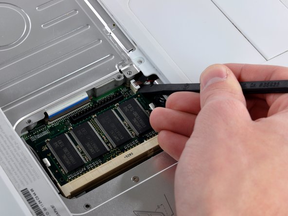
Using a spudger, pry up the AirPort/Bluetooth board from the end closest to the hard drive. Be sure to pry against the metal framework, as shown in the picture.
-
-
Este paso está sin traducir. Ayuda a traducirlo
-
Hold the AirPort/Bluetooth board in one hand and use a spudger to disconnect the two antenna cables.
-
-
Este paso está sin traducir. Ayuda a traducirlo
-
Lift the AirPort antenna cables off the heat sink and set them aside.
-
Lift the metal restraining bracket from the hard drive and place it aside.
-
-
Este paso está sin traducir. Ayuda a traducirlo
-
Remove the two Phillips screws from the white plastic fingers of the hinge grill.
-
-
Este paso está sin traducir. Ayuda a traducirlo
-
Remove the following 7 screws and 2 nuts from the heat sink:
-
One 3.5 mm Phillips from the lower left corner of the heat sink.
-
Five 6 mm Phillips from around the fan and at the center of the heat sink.
-
One 7.5 mm Phillips at the top right corner of the heat sink.
-
Two 4 mm screw nuts with attached springs from either side of the heat sink.
-
-
Este paso está sin traducir. Ayuda a traducirlo
-
Use a spudger to pry the heat sink up on the left side, near the hard drive.
-
-
Este paso está sin traducir. Ayuda a traducirlo
-
Grasp the heat sink in one hand and lift up the hinge grill in the other hand so that you can remove the heat sink from the computer.
-
-
Este paso está sin traducir. Ayuda a traducirlo
-
Remove the two Phillips screws securing the white plastic fingers of the I/O bezel to the metal framework.
-
-
Este paso está sin traducir. Ayuda a traducirlo
-
Lift up the left side of the computer and slide the I/O bezel away.
-
-
Este paso está sin traducir. Ayuda a traducirlo
-
Remove the single Phillips screw securing the EMI finger to the metal framework.
-
Lift the silver EMI finger off of the metal framework.
-
-
Este paso está sin traducir. Ayuda a traducirlo
-
Wedge a spudger between the RJ-11 board and the metal framework and slide the RJ-11 board down and off of the logic board.
-
-
Este paso está sin traducir. Ayuda a traducirlo
-
Remove the four Phillips screws securing the hard drive to the metal framework.
-
-
Este paso está sin traducir. Ayuda a traducirlo
-
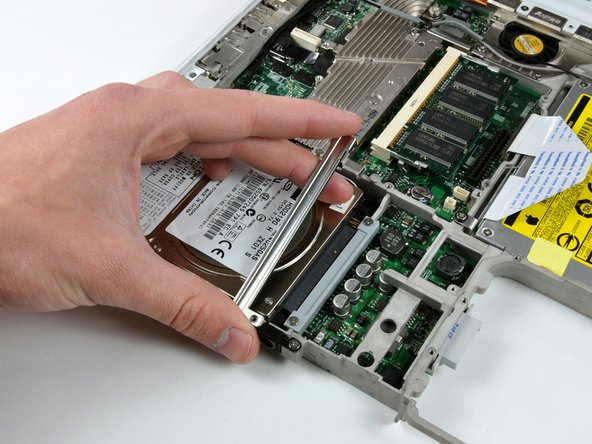
Slightly lift the hard drive from the free end and pull the hard drive straight away from the connector.
-
-
Este paso está sin traducir. Ayuda a traducirlo
-
Disconnect the microphone cable at the front of the computer, between the left side of the hard drive and the metal framework.
-
-
Este paso está sin traducir. Ayuda a traducirlo
-
Use the black plastic handle to disconnect the display data cable from the logic board.
-
-
Este paso está sin traducir. Ayuda a traducirlo
-
This is a diagram of the ribbon clamp connector you will disconnect in the next step.
-
1) With your fingernails, grasp the locking bar on either side and pull up a small amount (about 1/16" or 2 mm).
-
2) After disengaging the locking bar, slide the cable out of the connector.
-
-
Este paso está sin traducir. Ayuda a traducirlo
-
Release the optical drive ribbon clamp as described above. Slide the optical drive ribbon out of its connector.
-
-
Este paso está sin traducir. Ayuda a traducirlo
-
Close the display and flip the computer over.
-
Remove the following 12 screws:
-
Nine 3 mm Phillips.
-
One 3 mm Phillips with a thicker shaft at the bottom right corner of the logic board, next to the fan.
-
Two 7.5 mm Phillips on either side of the battery connector.
-
-
Este paso está sin traducir. Ayuda a traducirlo
-
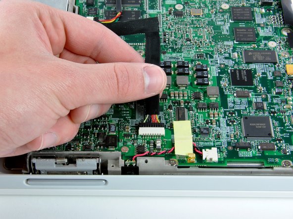
Disconnect the inverter, fan, and sleep light cables from the logic board.
-


Cancelar: No complete esta guía.
24 personas más completaron esta guía.
