Esta versión puede contener ediciones incorrectas. Cambie a la última instantánea verificada.
Qué necesitas
-
Este paso está sin traducir. Ayuda a traducirlo
-
Unscrew the two 4.0mm Phillips head screws found near the ports at the bottom of the device using a PH #00 screwdriver.
-
-
Este paso está sin traducir. Ayuda a traducirlo
-
Slide the plastic prying tool in between the front and back panel and pry them apart on all 4 sides.
-
It may be easiest to start on one of the sides, and work your way around the device. The bottom, with the ports, is the most difficult side and can be saved for last.
-
-
Este paso está sin traducir. Ayuda a traducirlo
-
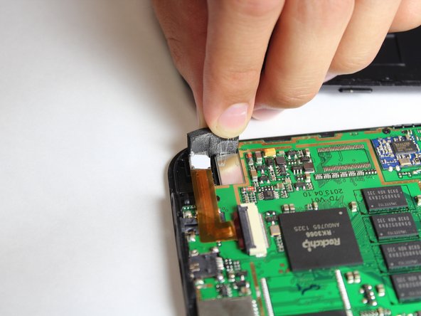
Remove the black pad on the back of the camera by peeling it off.
-
-
Este paso está sin traducir. Ayuda a traducirlo
-
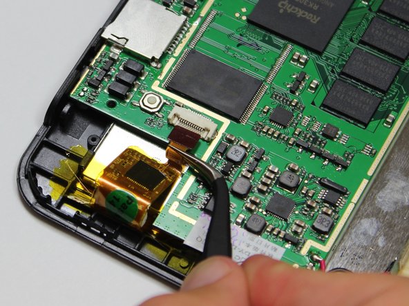
With the bottom of the device facing away from you, pull the camera out of its black housing.
-
-
Este paso está sin traducir. Ayuda a traducirlo
-
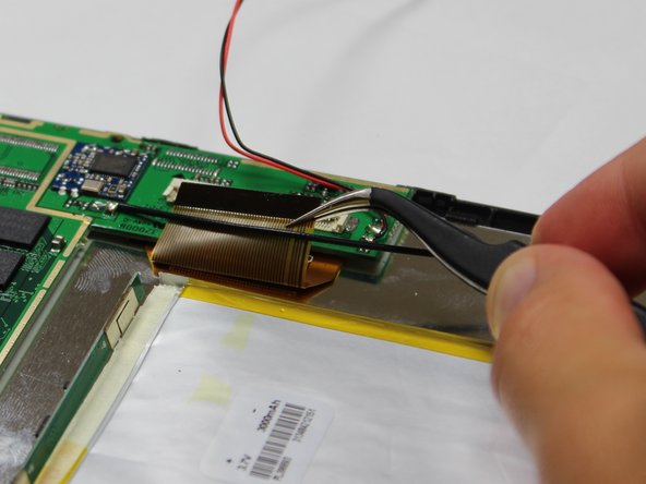
Use the tweezers to lift the grey connector, connecting the camera ribbon to the circuit board, up from the beige housing. It should rotate up, and allow you to slide the ribbon out from under the connector.
-
-
-
Este paso está sin traducir. Ayuda a traducirlo
-
Remove the three 4.0mm screws holding down the circuit board with the Phillips #00 screwdriver.
-
-
Este paso está sin traducir. Ayuda a traducirlo
-
Use the tweezers to lift the grey connector, located near the battery and speaker, up from the beige housing. It should rotate up, and allow you to slide the ribbon out from under the connector.
-
-
Este paso está sin traducir. Ayuda a traducirlo
-
Use the tweezers to lift the grey connector, located near the reset button, up from the beige housing. It should rotate up, and allow you to slide the ribbon out from under the connector.
-
-
Este paso está sin traducir. Ayuda a traducirlo
-
Turn the device around, and use the large plastic opening tool to pry the battery off of the back of the silver LCD.
-
-
Este paso está sin traducir. Ayuda a traducirlo
-
Lift the circuit board and the battery off of the front panel.
-
-
Este paso está sin traducir. Ayuda a traducirlo
-
Remove the two 3.0mm screws holding down the black tabs using the Phillips #00 screwdriver.
-
-
Este paso está sin traducir. Ayuda a traducirlo
-
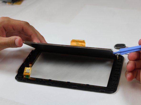
Use the Plastic Opening Tool to gently pry the black hooks away from the edges of the silver LCD. Then lift the LCD off of the front panel.
-
-
Este paso está sin traducir. Ayuda a traducirlo
-
Desolder the black wire from the LCD.
-
For soldering information, see our guide: Cómo soldar y desoldar conexiones.
-


Cancelar: No complete esta guía.
Una persona más ha completado esta guía.
Equipo

Cal Poly, Team 10-41, Amido Fall 2014 Miembro de Cal Poly, Team 10-41, Amido Fall 2014
CPSU-AMIDO-F14S10G41
4 Miembros
12 Guías creadas