Saltar al contenido principal

why! N131WU/BU/ZU Upper Case Replacement

Qué necesitas

  1. why! N131WU/BU/ZU Upper Case Replacement, Remove the Screws: paso 1, imagen 1 de 1
    • Remove the case screws (red) and the keyboard screws (green).

    • Be sure not to lose these screws. You will need them to reassemble your laptop.

  2. why! N131WU/BU/ZU Upper Case Replacement, Remove the Keyboard: paso 2, imagen 1 de 3 why! N131WU/BU/ZU Upper Case Replacement, Remove the Keyboard: paso 2, imagen 2 de 3 why! N131WU/BU/ZU Upper Case Replacement, Remove the Keyboard: paso 2, imagen 3 de 3
    • Using the hole provided under the case (see picture), push the keyboard out using a thin screwdriver or some other solid object.

    • Hold onto the keyboard as you push the keyboard so as not to damage the two cables still attached.

  3. why! N131WU/BU/ZU Upper Case Replacement, Remove Keyboard Connections: paso 3, imagen 1 de 3 why! N131WU/BU/ZU Upper Case Replacement, Remove Keyboard Connections: paso 3, imagen 2 de 3 why! N131WU/BU/ZU Upper Case Replacement, Remove Keyboard Connections: paso 3, imagen 3 de 3
    • (Blue Cable) Push up on the thin black portion on the connector and gently pull out the blue ribbon cable until it comes out.

    • (Orange Cable) Remove the orange cable by sliding the gray part of the connector towards the screen, then gently pull on the ribbon cable.

  4. why! N131WU/BU/ZU Upper Case Replacement, Remove the upper screws: paso 4, imagen 1 de 2 why! N131WU/BU/ZU Upper Case Replacement, Remove the upper screws: paso 4, imagen 2 de 2
    • Unscrew the three screws that were under the keyboard. Be sure to hold onto these.

    • After these are removed, you can now remove the lower part of the case from the rest of the computer.

  5. why! N131WU/BU/ZU Upper Case Replacement, Remove the SSD: paso 5, imagen 1 de 3 why! N131WU/BU/ZU Upper Case Replacement, Remove the SSD: paso 5, imagen 2 de 3 why! N131WU/BU/ZU Upper Case Replacement, Remove the SSD: paso 5, imagen 3 de 3
    • Remove the screw holding in the ssd.

    • Carefully remove the SSD from the connector.

  6. why! N131WU/BU/ZU Upper Case Replacement, RAM (Memory): paso 6, imagen 1 de 3 why! N131WU/BU/ZU Upper Case Replacement, RAM (Memory): paso 6, imagen 2 de 3 why! N131WU/BU/ZU Upper Case Replacement, RAM (Memory): paso 6, imagen 3 de 3
    • Gently pull outwards on the clips to free the RAM stick.

    • Remove the RAM Stick from its slot.

  7. why! N131WU/BU/ZU Upper Case Replacement, Battery: paso 7, imagen 1 de 2 why! N131WU/BU/ZU Upper Case Replacement, Battery: paso 7, imagen 2 de 2
    • Remove the five Phillips screws securing the battery.

    • Unplug the power connector and lift the battery out in the direction of the arrows to remove it.

  8. why! N131WU/BU/ZU Upper Case Replacement, Motherboard: paso 8, imagen 1 de 3 why! N131WU/BU/ZU Upper Case Replacement, Motherboard: paso 8, imagen 2 de 3 why! N131WU/BU/ZU Upper Case Replacement, Motherboard: paso 8, imagen 3 de 3
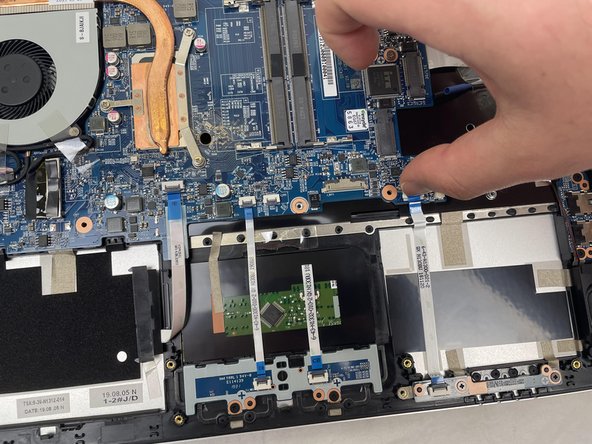
    • Lift the retaining latch and unplug the ZIF cable found under the keyboard.

    • Disconnect the nine marked cables as detailed in the following steps.

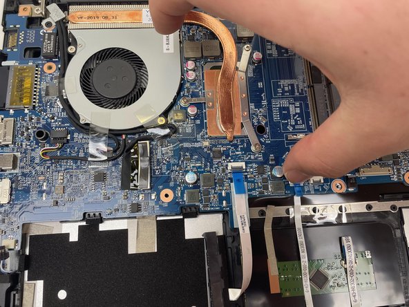
    • Remove the four screws securing the motherboard to the case.

  9. why! N131WU/BU/ZU Upper Case Replacement, ZIF Connectors: paso 9, imagen 1 de 3 why! N131WU/BU/ZU Upper Case Replacement, ZIF Connectors: paso 9, imagen 2 de 3 why! N131WU/BU/ZU Upper Case Replacement, ZIF Connectors: paso 9, imagen 3 de 3
    • The cables with the blue reinforcing tabs are ZIF connectors that require you to lift the retaining lever before removing the cable.

  10. why! N131WU/BU/ZU Upper Case Replacement, SATA Cable: paso 10, imagen 1 de 3 why! N131WU/BU/ZU Upper Case Replacement, SATA Cable: paso 10, imagen 2 de 3 why! N131WU/BU/ZU Upper Case Replacement, SATA Cable: paso 10, imagen 3 de 3
    • Remove the SATA3 cable from the motherboard after disconnecting it.

  11. why! N131WU/BU/ZU Upper Case Replacement, Motherboard (continued): paso 11, imagen 1 de 2 why! N131WU/BU/ZU Upper Case Replacement, Motherboard (continued): paso 11, imagen 2 de 2
    • Don't forget to remove these cables.

  12. why! N131WU/BU/ZU Upper Case Replacement, Display Connector: paso 12, imagen 1 de 2 why! N131WU/BU/ZU Upper Case Replacement, Display Connector: paso 12, imagen 2 de 2
    • Note: The original instructions call for inserting your thumbnail firmly under the base of the display connector

    • However, the proper way to remove the display connector is to grasp the plastic strap on top of the connector and use it to pull the connector straight up.

  13. why! N131WU/BU/ZU Upper Case Replacement, Remove the Motherboard: paso 13, imagen 1 de 3 why! N131WU/BU/ZU Upper Case Replacement, Remove the Motherboard: paso 13, imagen 2 de 3 why! N131WU/BU/ZU Upper Case Replacement, Remove the Motherboard: paso 13, imagen 3 de 3
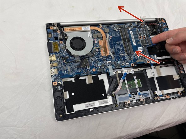
    • Once the screws have been removed, carefully lift the motherboard from the end indicated by the arrows.

    • Remember to disconnect the cables near the fan.

  14. why! N131WU/BU/ZU Upper Case Replacement, Motherboard (continued): paso 14, imagen 1 de 1
    • The motherboard has been successfully removed.

  15. why! N131WU/BU/ZU Upper Case Replacement, Speakers: paso 15, imagen 1 de 3 why! N131WU/BU/ZU Upper Case Replacement, Speakers: paso 15, imagen 2 de 3 why! N131WU/BU/ZU Upper Case Replacement, Speakers: paso 15, imagen 3 de 3
    • Remove the right speaker.

    • To remove the left speaker, first peel off the microphone/headset cable, then the adhesive strips.

  16. why! N131WU/BU/ZU Upper Case Replacement, Speaker/Fan/Headset connector: paso 16, imagen 1 de 3 why! N131WU/BU/ZU Upper Case Replacement, Speaker/Fan/Headset connector: paso 16, imagen 2 de 3 why! N131WU/BU/ZU Upper Case Replacement, Speaker/Fan/Headset connector: paso 16, imagen 3 de 3
    • Remove the left speaker.

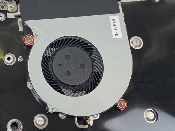
    • Remove the two Phillips screws securing the CPU fan to the case and remove the fan.

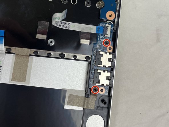
    • Remove the two screws securing the audio connector board.

  17. why! N131WU/BU/ZU Upper Case Replacement, Headset and USB Boards: paso 17, imagen 1 de 3 why! N131WU/BU/ZU Upper Case Replacement, Headset and USB Boards: paso 17, imagen 2 de 3 why! N131WU/BU/ZU Upper Case Replacement, Headset and USB Boards: paso 17, imagen 3 de 3
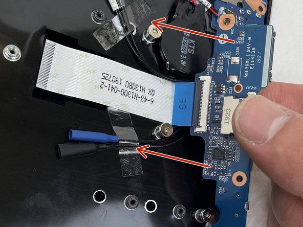
    • Lift the audio board at the point indicated by the red arrow and slide it away from the chassis in the direction of the orange arrow.

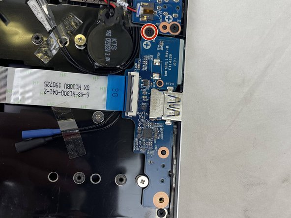
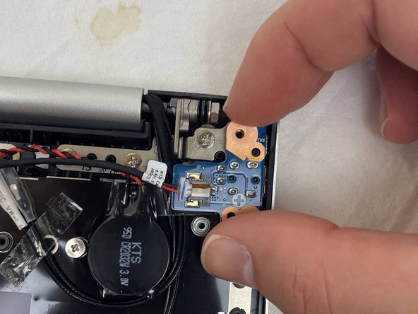
    • Remove the Phillips screw securing the power connector board.

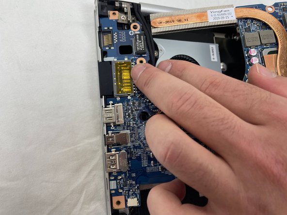
    • Lift out the USB connector board in the direction indicated by the arrows.

    • The ribbon cable is secured to the upper case with adhesive. It is not necessary to disconnect it from the USB board; just carefully peel the entire assembly from the case in the direction of the arrows.

  18. why! N131WU/BU/ZU Upper Case Replacement, DC Board and CMOS Battery: paso 18, imagen 1 de 3 why! N131WU/BU/ZU Upper Case Replacement, DC Board and CMOS Battery: paso 18, imagen 2 de 3 why! N131WU/BU/ZU Upper Case Replacement, DC Board and CMOS Battery: paso 18, imagen 3 de 3
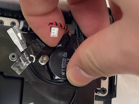
    • Unplug the DC input board, remove the single Phillips screw securing it and remove it.

    • The DC power wires can remain in place.

    • The CMOS battery is secured to the case with adhesive. Simply peel it off to remove it.

  19. why! N131WU/BU/ZU Upper Case Replacement, LED Board / Touchpad Button Plate: paso 19, imagen 1 de 3 why! N131WU/BU/ZU Upper Case Replacement, LED Board / Touchpad Button Plate: paso 19, imagen 2 de 3 why! N131WU/BU/ZU Upper Case Replacement, LED Board / Touchpad Button Plate: paso 19, imagen 3 de 3
    • Remove the two screws holding the LED board on the chassis and remove it along with the ribbon cable.

    • No force is necessary; it is lightly adhered to the board and can easily be peeled off.

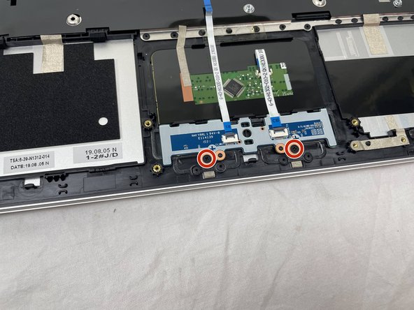
    • Remove the two screws securing the touchpad button plate.

  20. why! N131WU/BU/ZU Upper Case Replacement, Touchpad Button Board: paso 20, imagen 1 de 3 why! N131WU/BU/ZU Upper Case Replacement, Touchpad Button Board: paso 20, imagen 2 de 3 why! N131WU/BU/ZU Upper Case Replacement, Touchpad Button Board: paso 20, imagen 3 de 3
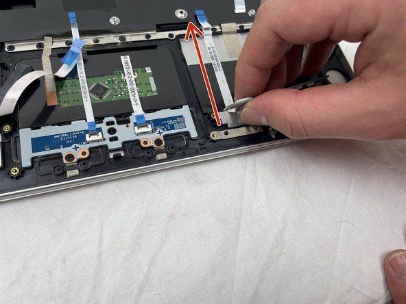
    • Lift the ZIF connector retaining tab and unplug the button cable on the right.

    • Grasp the LED board between the two cables.

    • Following the direction of the red arrow, peel the two cables from the case.

  21. why! N131WU/BU/ZU Upper Case Replacement, Cable Tapes / Hinge Screws: paso 21, imagen 1 de 3 why! N131WU/BU/ZU Upper Case Replacement, Cable Tapes / Hinge Screws: paso 21, imagen 2 de 3 why! N131WU/BU/ZU Upper Case Replacement, Cable Tapes / Hinge Screws: paso 21, imagen 3 de 3
    • Peel off the pieces of tape holding the cables onto the chassis.

    • Remove the six Phillips screws securing the hinges, three on each side.

  22. why! N131WU/BU/ZU Upper Case Replacement, Upper Case: paso 22, imagen 1 de 3 why! N131WU/BU/ZU Upper Case Replacement, Upper Case: paso 22, imagen 2 de 3 why! N131WU/BU/ZU Upper Case Replacement, Upper Case: paso 22, imagen 3 de 3
    • While holding down the display, lift the chassis up to about a 45 degree angle.

    • The case will slide out once there is sufficient clearance.

Conclusión

To reassemble your device, follow these instructions in reverse order.

Una persona más ha completado esta guía.

Un agradecimiento especial a estos traductores:

fr en

100%

Estos traductores nos están ayudando a reparar el mundo! ¿Quieres contribuir?
Empezar a traducir ›

Felice Suglia

Miembro Desde 06/15/13

30,908 Reputación

264 Guías creadas

0 comentarios

Agregar Comentario

Ver Estadísticas:

Ultimas 24 horas: 0

Ultimos 7 días: 2

Ultimos 30 días: 16

Todo El Tiempo: 167