Introducción
In the ENVY 15 j100el model the graphic card GeForce GT 740M can provide the display connected through the LVDS interface with a resolution up to 1920 x 1200 with the easy withstanding of the processor which can also handle bigger resolutions.
Therefore, since the fact that your hardware can support it, if you have to replace the original LG LP156WH3(TL)(S2) panel display, which has a native resolution of 1366×768 (HD), you could consider to upgrade it to a Full HD display with a 1920x1080 (FHD) native resolution.
The new display should have these characteristics:
- Size: 15.6"
- Form Style: Slim or flat
- Signal interface: LVDS, 40 pins connector (1 or 2 channels)
- Operating mode: transmissive (it can be then either normally black or white, either IPS or TN also)
- Frequency: 60 Hz
- Input Voltage: 3.3V
- Light source: White light-emitting diode (WLED) with LED driver
- No touch screen
Besides the previous restrictions you are free to choose about brightness, viewing angle, colours range, surface treatment, contrast ratio, response time, resolution (the latter one up to a max of 1920x1200 due to the graphic card) and so on.
The best display panel that this HP model could afford would probably be the B156HAN01.0 produced by AUO due to its wide viewing angle, IPS technology, high contrast ratio and better colour performance but this screen was only produced until 2013 and it’s hard to find nowadays. I managed to find this panel on eBay and after its installation the result was really good - viewing angle and colours were fantastic - but unfortunately it was not functioning in the middle (a small black vertical stripe was there). So, in the end, I installed a B156HTN03.3 which is not as good as the above-mentioned one but a whole lot better than the original LG display. Choose your best one!
If you only want to replace the display panel
jump directly to step#23 ─ in any case only after having removed the battery in order to avoid short circuits on the display cable once you will be handling it ─ and try to install the new LCD without opening the laptop. It’s quite difficult because two of the four screws that secure the display bezel are hard to reach without splitting the laptop in two but you could manage to loosen them somehow.
On the contrary, if you have to replace the display cable also,
bear in mind that you will need to replace the thermal paste too and therefore, before starting, gather together all the tools that you will need for that too. In order to work on the display hinges with ease, we have to indeed disassemble the heatsink and the fan. You can find the standard display cable for sale on e-commerce using the following HP part number: 720536-001.
Qué necesitas
-
-
Turn the laptop upside down and gently lay it down on a flat surface.
-
Slide the battery release latch to the right and the battery will pop up slightly.
-
While keeping the latch slid with one hand, grab the battery with the other hand and remove it by pivoting it upward.
-
-
-
Remove the Phillips PM2.0×4.0 screw using a PH#00 screwdriver.
-
-
-
With an opening tool pry off the tabs that secure the service door to the base enclosure. Start with the long edge.
-
Continue along the short edges.
-
Once you have pried the service door off as it is in pic#3, it will come out of the rear edge very easily.
-
-
-
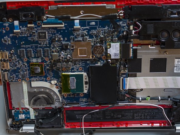
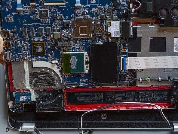
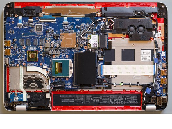
RAM memory modules
-
HDD (Hard Disk Drive)
-
mSATA SSD slot
-
Wifi & BT module (Wireless card)
-
-
-
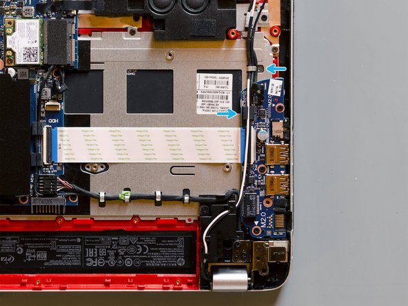
Are you grounded? If yes, using a spudger, flip up the small black locking flap of the hard disk's ZIF connector.
-
Afterwards, using a pair of tweezers, grab the HDD's SATA cable at the transparent tab and simply lift its end up, out of the connector.
-
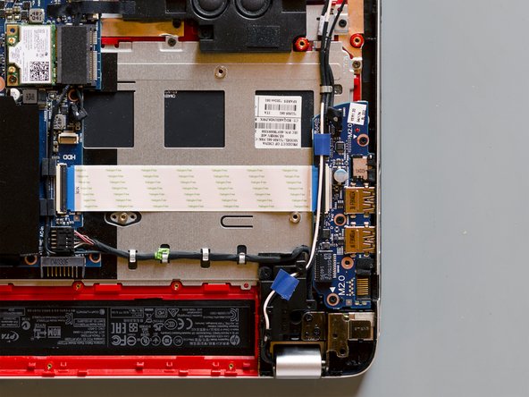
By levering with an opening tool, pry the HDD out of its bay. Once it is on your hand, release its cable from its retaining hole obtained on the base enclosure and finally leave the HDD aside.
-
-
-
Using a PH#00 screwdriver remove the Phillips PM 2.0x2.5 screw which secures the SSD to the base enclosure: the SSD module will tilt up immediately.
-
Once the module is standing ─ if you're grounded ─ grab it with your fingers as it is shown in pic#3 and slowly pull it out of its connector maintaining its inclination.
-
On top of the previous movement - and always maintaining the SSD tilted - you have to lightly move the module back and forward as the blue arrow shows: think of a pendulum.
-
-
-
Using a PH#00 screwdriver remove the two Phillips PM2.5x5 screws of the service door area. Group these screws together.
-
Using a PH#00 screwdriver remove the three remaining Phillips PM2.5x3 screws of the service door area. Group these screws together.
-
Using a PH#000 screwdriver remove the seven small Phillips PM1.5x2 screws of the battery bay. Group these screws together.
-
-
-
Pry both of the top rubber pads off with a metal spudger. They are attached to the base enclosure with adhesive.
-
Using a PH#00 screwdriver remove then the eight Phillips PM2.5x5 screws that secure the base enclosure to the laptop. Group these screws together.
-
-
-
By gently levering with opening tools, disengage the tabs that secure the base enclosure to the laptop. Start with the longer edge. Feel free to use your hands and to lift or turn the laptop if you like.
-
Once you have completed the long edge, proceed along the short edges. When also these two sides will be detached, the base enclosure will come out from the bottom edge with ease.
-
-
-
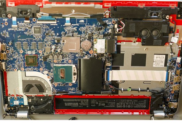
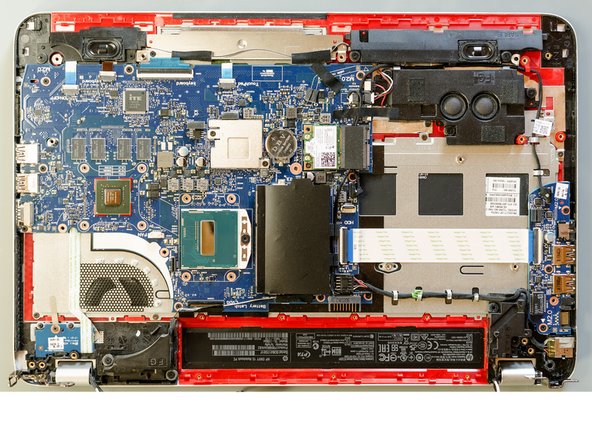
Before dismounting anything it is better to clean all the parts. Are you grounded? If yes, take an antistatic brush and dust off all that you can.
-
-
-
Detach the adhesive stripe that secures the webcam's and the display's cable to the fan.
-
Disconnect the fan's ribbon connector. It would be better if you would follow this method (step#2) but if you do not properly manage to grab the connector with your fingers, take two pairs of tweezers, grab all the wires as close as possible to the connector ─ as it is shown in pic#2 ─ and resolutely pull them straight up.
-
Using a PH#00 screwdriver remove the two Phillips PM2.5×4.5 screws and group them together.
-
Using a PH#00 screwdriver remove the last Phillips PM2.5×6.5 screw that secure the fan to the top cover. Do not group it together with the two previous screws because it is longer than those.
-
-
-
Using a PH#00 screwdriver unfasten the eight not-releasable screws that secure the heatsink to the motherboard. Nearby the screws you will notice that numbers have been impressed: the screw marked in red is the first one that has to be unfastened, follow then the order.
-
Once you are done with the screws, grab the heatsink and the fan as it is shown in pic#2, tilt them up a bit, and carefully slide them forward a little: until the fan is free of the left display hinge marked in green in pic#1. Finally then, rise them up and put them aside.
-
-
-
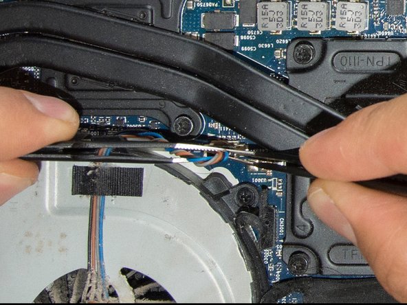
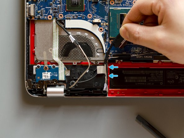
Using both, a pair of tweezers and your fingers, detach the adhesive which covers the display's ZIF connector. Be careful not to damage the two thin wires which are also held down by the adhesive.
-
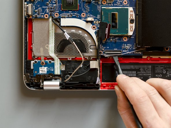
Then, using a spudger, flip up the locking flap of the connector by prying it open. It's possible that it won't disconnect at once because it is quite a firm and long connector. If it is so, don't force it, but gently pry it open to the sides also.
-
-
-
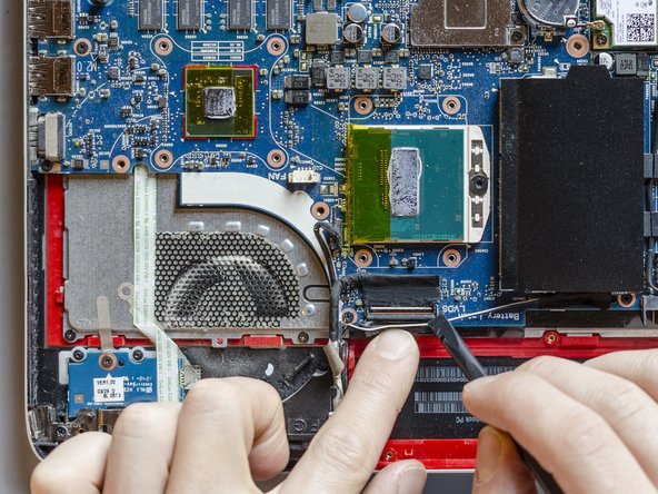
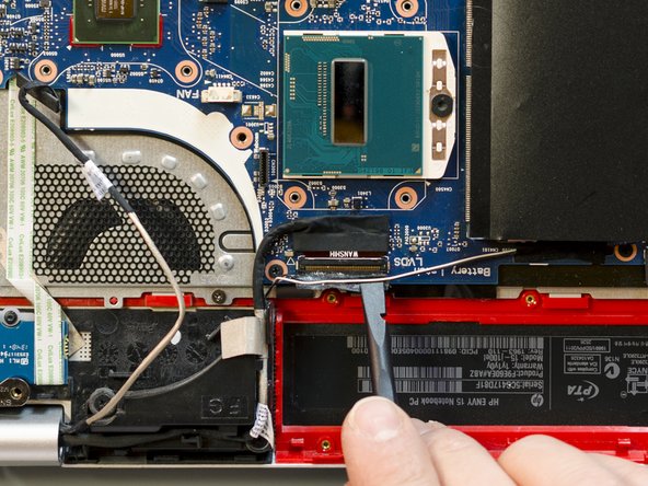
Using a pair of tweezers, grab the display cable in the middle and lift it up in order to take it out of the connector.
-
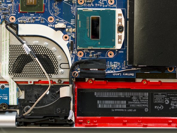
Release now the display cable from its routing channel up to the left hinge. Pull it out using your hands and by getting round the plastic clips.
-
-
-
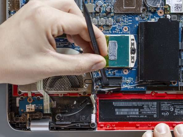
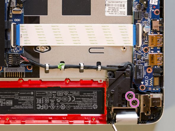
In order to disconnect the ribbon connector of the webcam cable, grab it as it is shown in pic#1 and ─ by swinging it a bit back and forth ─ pull it up powerfully.
-
Release then the webcam cable from the routing channel up to the left hinge as you earlier did for the display cable.
-
(The purple-bullet-info is in the next step)
-
-
-
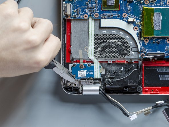
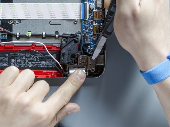
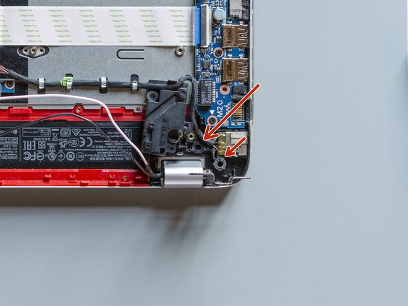
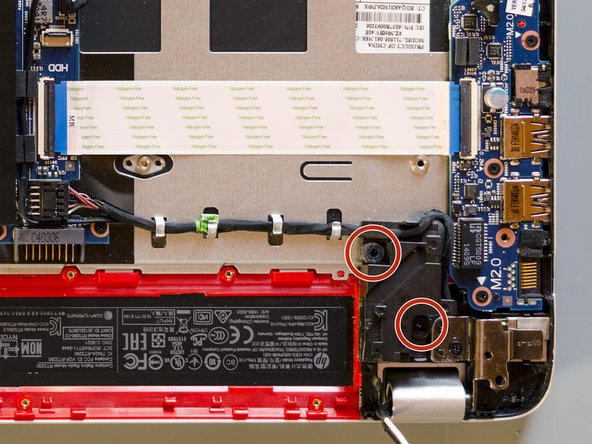
Using a PH#00 screwdriver remove the Phillips PM2.5×4.5 screw which lastly secures the left hinge of the display to the top cover. The screw is visible in the last picture of the previous step.
-
Using the small pliers grab the left hinge in the middle and pull it up as far as it opens. The hinge is quite hard to turn so feel free to move around to find the best grip. Only remember not to grab the hinge too far from its pivoting point, because you could bend it by prying it away from elsewhere.
-
-
-
-
Are you grounded? If yes, using a pair of tweezers grab one of the two wireless antenna cables at its golden end and take it out by pulling it up strongly and resolutely.
-
Repeat the same operation on the other cable.
-
-
-
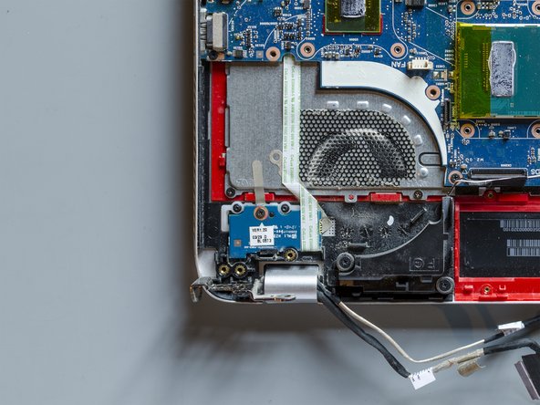
Using a pair of tweezers detach the adhesive stripe that holds down the antenna cables on the motherboard.
-
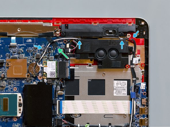
Using your hands ─ and paying attention to clips and intersections with other cables ─ begin to release the wireless antenna cables from their routing channel built between the subwoofer and left front speaker.
-
-
-
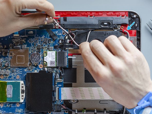
Carry on the removal of the wireless antenna cables releasing them from eventual intersections with other cables and from the clips built into the top cover and the connector board. Use a spudger to separate them from the other cables if you like.
-
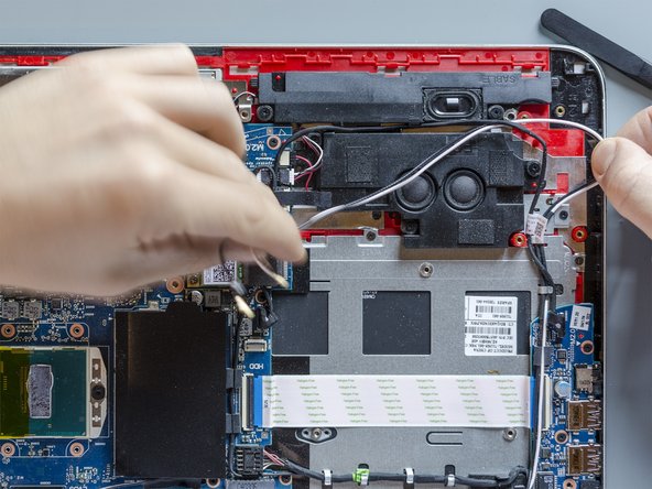
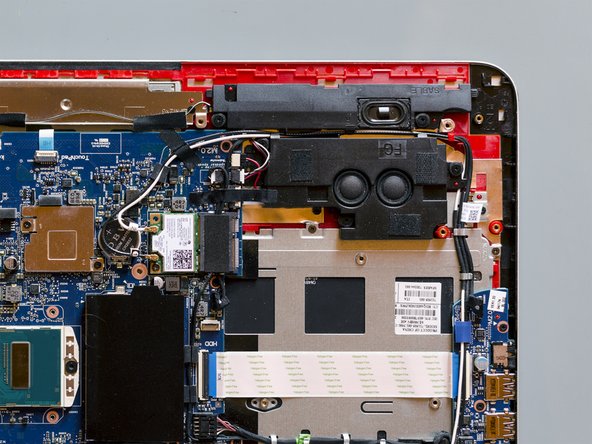
Conclude the removal by releasing the antenna cables from the clips and the routing channel built into the left rear speaker.
-
-
-
Using a PH#00 screwdriver remove the two screws that secure the left rear speaker to the top cover. Group these screws together.
-
Now, using your hand, drift the speaker towards left a bit in order to be able in the next step to use the pliers on the right hinge with ease.
-
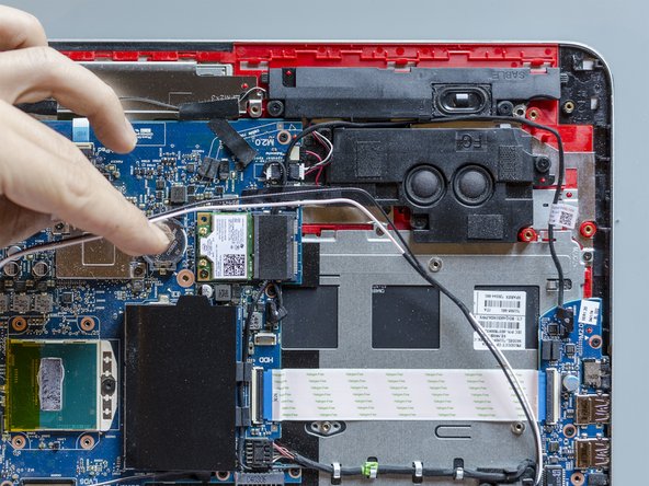
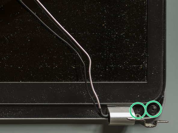
Using a PH#00 screwdriver remove the two Phillips PM2.5x4.5 that secure the right hinge to the top cover. You can group these screws together with the one we removed from the left hinge in the step#16: they are identical.
-
-
-
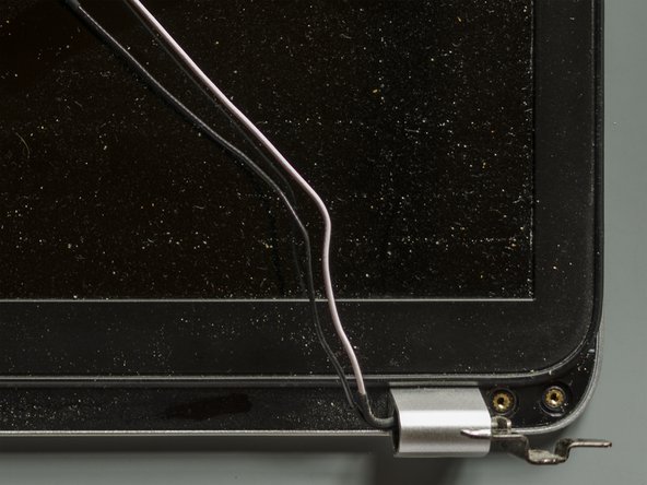
Using the small pliers grab the right hinge in the middle and pull it up as far as it opens. Observe the same precautions you followed opening the left display hinge: grab it in the middle only.
-
While the hinge is being pulled, this small centring pin has to come out of it. Keep an eye on it because it can easily break. You could use a metal spudger behind the hinge to hold the plastics down while you're raising the hinge if you like.
-
-
-
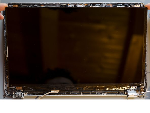
Now the top cover is completely disconnected from the display panel and it is free to move. Grab it at the short edges and take it out of the display hinges by sliding it forward and tilting it up a little.
-
Leave it then aside for a while.
-
-
-
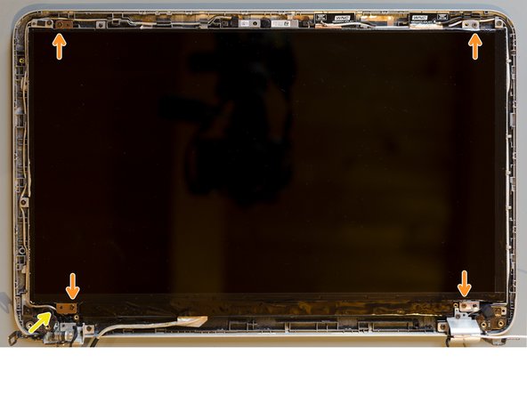
Start from one of the two bottom corners. Using a pair of tweezers remove the custom adhesive shield that covers the screws.
-
Using a PH#00 screwdriver remove the two Phillips PM2.5×3.2 broad head screws that secure the display bezel to the display assembly.
-
Repeat the same operation on the other corner in order to remove all of the four broad head screws that secure the display bezel and group these screws together.
-
-
-
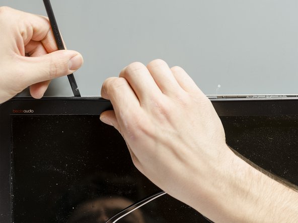
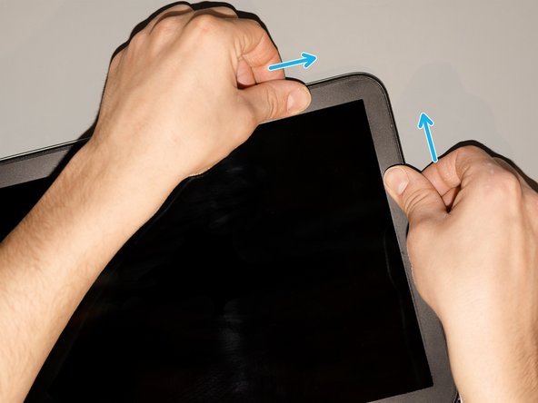
Using your fingers and a spudger, or any other opening tool, pry the bezel away from the display enclosure. First start from one of the two top corners and go along the long edge. Do not push the opening tool too much inside, its tip is already enough to disengage the tabs of the bezel.
-
Once the top edge is disconnected, disengage the short edges of the bezel, one at a time.
-
Leave then the bottom edge still connected to the display panel as it is shown in pic#3.
-
-
-
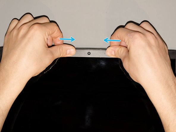
There is a thick adhesive stripe that attaches the bottom edge of the bezel to the display panel. Therefore, keeping the bezel tilted up a bit with one hand, detach the tape from the bezel using the other hand trying to leave the adhesive attached to the display. Start from a corner and go slowly along the edge.
-
-
-
Using a PH#00 screwdriver remove the four Phillips PM2.0×2.9 screws that secure the display panel to its enclosure. Group these screws together.
-
-
-
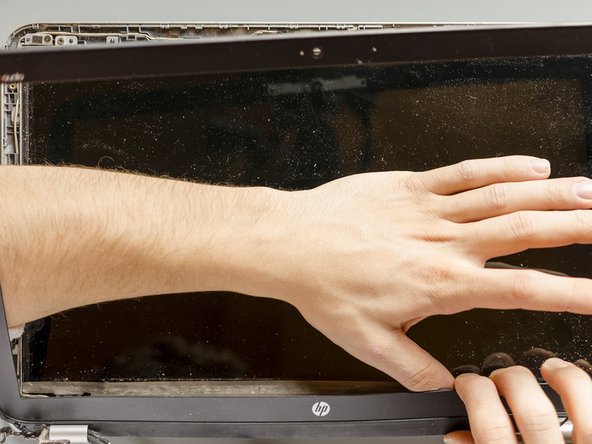
Using a spudger, lift one of the top corners of the display panel until you manage to grab the latter one with your fingers.
-
By making it pivot at the bottom, turn then the old display panel upside down and gently lay it down on your table.
-
-
-
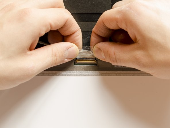
First, using your fingers, detach the adhesive stripe that reinforces the connection.
-
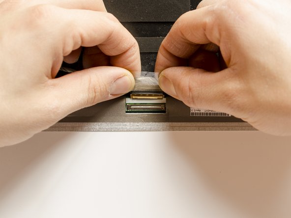
Are you grounded? If yes, grabbing both, the display cable and its adhesive stripe ─ as it is shown in pic#2 ─ straightly and resolutely pull the display cable out of its connector.
-
The old display panel is now detached and you can leave it aside.
-
-
-
Using a PH#00 screwdriver remove the Phillips PM2.0×2.9 screw that secures the left hinge cap to the display enclosure.
-
Grab then the left hinge cap with your fingers and, by forcefully pulling it out, disengage it from the display enclosure. Leave it aside for a while.
-
-
-
Using your hands, first move the webcam cable aside and afterwards take the old display cable away.
-
-
-
Lay the new display panel over its packaging ─ or any other soft layer you have at hand ─ with its front side facing the table so that you have the display connector in front of you, as in pic#1.
-
Grab the end of the new cable with your fingers as you did with the old one, align it and push it inside the connector straightly and powerfully.
-
-
-
Using a pair of tweezers remove the shield of the adhesive stripe.
-
Then, using your fingers as shown in pic#2, attach the adhesive stripe over the connector and on the back of the display panel. Try to maintain the connection tight: while you are turning the stripe, keep pushing it straight forward also, as you just did to insert the cable in the connector.
-
-
-
Take the display enclosure and, if it's necessary, remove the dirt using a brush and a vacuum cleaner. Isopropyl alcohol would work well too but do not use it nearby the wifi antennas which are on the top right corner.
-
Take the new display and turn it down on the enclosure starting from the bottom, as it is shown in pic#2. Once all of the pins which stand nearby the screws' threads have passed through the metal tabs, the display is correctly positioned.
-
The webcam cable goes behind the display tab.
-
Finally secure the new display to its enclosure remounting the four Phillips PM2.0×2.9 screws using a PH#00 screwdriver.
-
-
-
Make the new display cable pass through its dedicated clips on the display enclosure.
-
Make the webcam cable go through its indentation obtained in the hinge and lay it over the display cable at the circular exit of the hinge.
-
-
-
Retrieve the left hinge cap and snap it back in its position. You should be able to hear a weak click when it gets rightly connected. If not, probably the cables don't let it snap properly due to their incorrect position.
-
Once the hinge cap is attached, reinsert its Phillips PM2.0×2.9 screw using a PH#00 screwdriver.
-
-
-
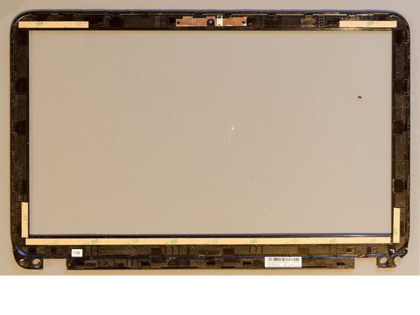
Remove the old double-sided adhesive tape which is on the internal side of the display bezel. Scrub it off using a stiff tool and isopropyl alcohol if it's necessary.
-
Once the bezel looks good, attach new stripes of double-sided tape on the same areas where the old ones were placed.
-
-
-
Remove the covers of the double-sided tape and lay the bezel over the display assembly. First lay down the bottom edge between the hinges which will help you to better centre the bezel and then make it turn down.
-
Afterwards, starting from the middle of the bottom edge and going towards the short edges, snap all the tabs of the bezel back into position. Finish the reassembly at the webcam and press a little over the areas where you laid the adhesive.
-
-
-
Secure now the bezel at its left corner with two of the four Phillips PM2.5×3.2 broad head screws using a PH#00 screwdriver. Afterwards, reattach the custom adhesive shield over the screws. If the latter one is not sticky anymore, add some double-sided tape.
-
Repeat the previous operation on the right corner of the display bezel.
-
-
-
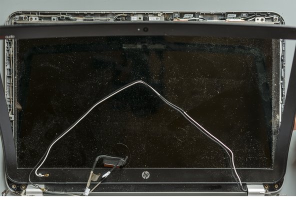
Draw all the wires which come out from the hinges away from the display panel.
-
Retrieve the top cover and place it over the display assembly. First lay its bottom down so that the hinges will help you to centre it properly and afterwards gently turn the top cover down over the display.
-
-
-
Using the small pliers grab the hinge in the middle and push it down. Once it is almost fully attached, finish the operation pressing its top with your fingers. If the centring pin manages to pass trough the hinge, top cover and display assembly are correctly aligned.
-
Using a PH#00 screwdriver reassemble two of the three Phillips PM2.5×4.5 screws in order to fasten the right display hinge to the top cover.
-
Once both of the hinges are fastened, set the left rear speaker in its original position and secure it to the top cover mounting its two screws.
-
-
-
Starting from the exit of the right hinge, guide the two wires together along their routing channel. Look out for and make use of all the clips.
-
-
-
Go on setting the cables in their channel built between the front speaker and the subwoofer. Use a spudger to push the antenna wires and the other cable with ease inside the two metal clips.
-
Reattach the adhesive stripe which holds the antenna wires tight to the mother board.
-
Once the wifi antenna cables have been correctly routed, connect them back to the wifi & BT module. Place the golden end of each wire over its coaxial connector and, using a spudger, simply press it down straightly and forcefully: they will loudly snap into their connectors. Look at pic#3 in order not to mix up the cables!
-
-
-
Starting from the left hinge, guide the display cable to its connector letting it pass though the clips of its routing channel.
-
Then get the connector ready: detach the adhesive tape which is over it and open its flap.
-
-
-
Lay the display cable's end inside the connector. It is rightly positioned when its two indentations match the two small black "squares" at the edges of the ZIF connector and when the white line visually creates a single line with the those "squares".
-
Then, keeping the cable positioned with one hand, push the locking flap down using a spudger. This operation has not to be done in one single movement: start pressing the middle of the flap and evenly proceed with its edges.
-
Once the flap of the connector is locked, reattach the adhesive tape over the connector. Mind the other two wires which it is also holding.
-
-
-
Place the webcam cable back in its routing channel, laying it over the display cable and letting it go through the same clips.
-
When the webcam cable meets the adhesive stripe of the display cable, let the former go behind the latter so that later, once you will be attaching this adhesive stripe over the fan, it will hold also the webcam cable in position.
-
Once the webcam cable is correctly positioned, grab its end as shown in pic#2 and push it inside its ribbon connector resolutely, with one single movement.
-
-
-
The job is done! The new display panel and its new cable are finally connected to the laptop. Only the new thermal paste layout and the final reassembly are missing.
-
It's only a matter of cleaning well the motherboard and laying down some new thermal compound. You can follow the steps for this operation at this link (step#12) Cheers!
-