Esta versión puede contener ediciones incorrectas. Cambie a la última instantánea verificada.
Qué necesitas
-
Este paso está sin traducir. Ayuda a traducirlo
-
Hold the device so the left side is facing towards you (like in the picture shown) so the two 4mm PH001 screws are exposed and easier to access.
-
-
-
Este paso está sin traducir. Ayuda a traducirlo
-
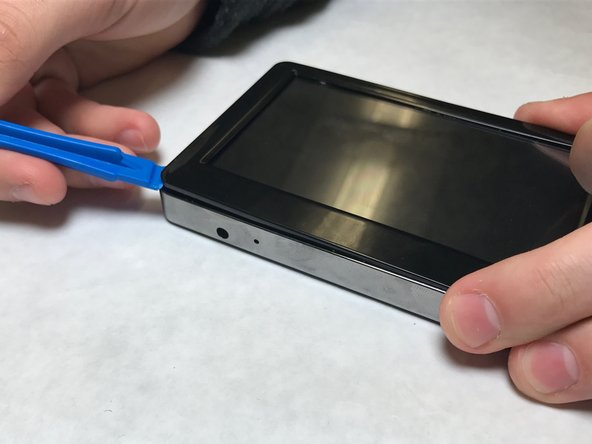
Carefully pry up one of the top corners of the screen with a plastic spudger (prying tool). Slide the tool along the edges to release it from the housing.
-
The screen is still connected to the motherboard. Use force with caution.
-
-
Este paso está sin traducir. Ayuda a traducirlo
-
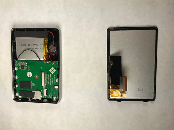
Gently turn screen over, to the side, to reveal the ZIF connector attached to the motherboard.
-
-
Este paso está sin traducir. Ayuda a traducirlo
-
Gently using tweezers, flip the black clip up. Pull the ZIF connector out.
-
-
Este paso está sin traducir. Ayuda a traducirlo
-
Using the prying tool, slide the black clip out. Pull the ZIF connector out and to the left, the screen is now detached from the motherboard.
-


Cancelar: No complete esta guía.
Una persona más ha completado esta guía.
Equipo

IUPUI, Team 1-4, Harley Fall 2016 Miembro de IUPUI, Team 1-4, Harley Fall 2016
IUPUI-HARLEY-F16S1G4
3 Miembros
8 Guías creadas