Esta versión puede contener ediciones incorrectas. Cambie a la última instantánea verificada.
Qué necesitas
-
Este paso está sin traducir. Ayuda a traducirlo
-
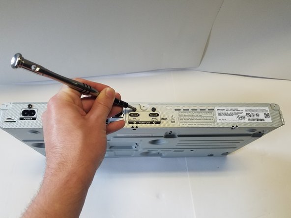
On the back side of the unit, remove the three 8.1mm screws marked with a Phillips #1 screwdriver.
-
-
Este paso está sin traducir. Ayuda a traducirlo
-
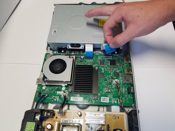
From the back, lift the case upwards away from the unit then forwards, releasing the prongs on the front.
-
-
Este paso está sin traducir. Ayuda a traducirlo
-
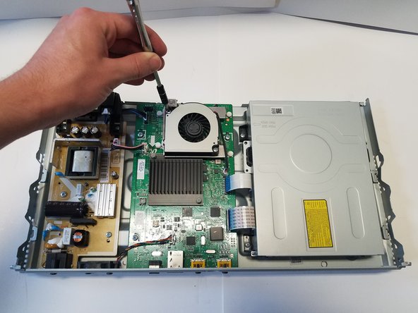
There is one group of wires located towards the front of the case and attached directly to the motherboard and the case. Using two fingers in a pinching motion, release the wire from the clip and disconnect it.
-
-
Este paso está sin traducir. Ayuda a traducirlo
-
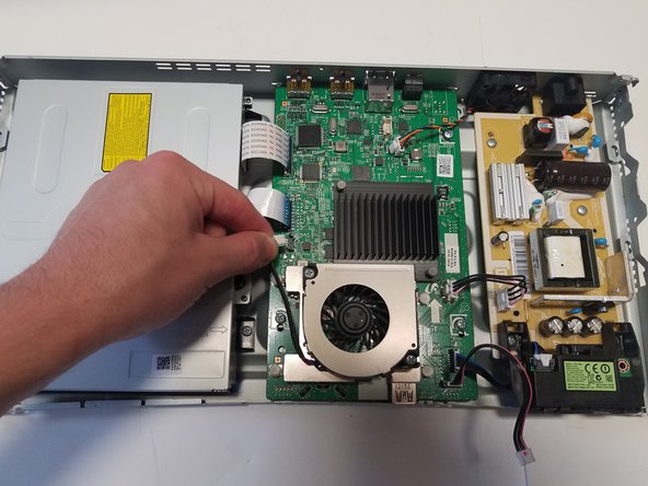
Fan A is located on top of the motherboard and is screwed into a stand by two 6.5mm screws. The stand is also connected to the motherboard.
-
-
-
Este paso está sin traducir. Ayuda a traducirlo
-
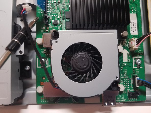
The two 6.5mm screws holding the fan in place on opposing corners must be removed with a #1 Phillips head screwdriver to change the fan.
-
-
Este paso está sin traducir. Ayuda a traducirlo
-
There is one wire connecting the fan to the motherboard that must be unplugged in order to release it. To unplug, use your fingers to pinch the white clip at the end and gently pull upwards to release.
-
-
Este paso está sin traducir. Ayuda a traducirlo
-
The motherboard is in the middle of the device and has all wires and connections of the device components running to it. The fan identified as fan A is located on top of it and must be removed first.
-
-
Este paso está sin traducir. Ayuda a traducirlo
-
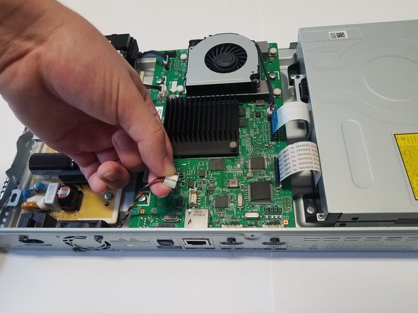
Once the fan is removed, the wires should be disconnected from the motherboard, as shown.
-
-
Este paso está sin traducir. Ayuda a traducirlo
-
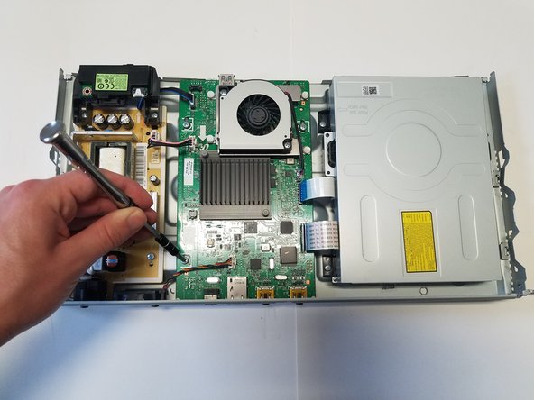
Two outer 8.1mm screws located above the HDMI ports hold the motherboard in place and must be removed. Remove these with a #1 Phillips head screwdriver.
-
-
Este paso está sin traducir. Ayuda a traducirlo
-
Three inner 6.5mm Phillips #1 screws hold the motherboard to the base of the frame, and must be unscrewed next.
-
-
Este paso está sin traducir. Ayuda a traducirlo
-
After the final screw is removed, the motherboard can be easily lifted out of the case without disturbing any of the other device components.
-


Cancelar: No complete esta guía.
Una persona más ha completado esta guía.
Equipo

Baylor, Team S2-G1, Johnson Spring 2018 Miembro de Baylor, Team S2-G1, Johnson Spring 2018
BU-JOHNSON-S18S2G1
3 Miembros
6 Guías creadas