Esta versión puede contener ediciones incorrectas. Cambiar a la última instantánea verificada.
Qué necesitas
-
Este paso está sin traducir. Ayuda a traducirlo
-
To soften the adhesive holding the tablet together, heat up the edges of the glass panel using a heated iOpener on the edge of the device. Alternatively you can use a heat gun to loosen the adhesive.
-
Leave the iOpener on edge for two minutes.
-
-
Este paso está sin traducir. Ayuda a traducirlo
-
Place a suction cup near edge that you heated up with the iOpener.
-
Press down on the suction cup to create a seal, and pull up with force to create a separation between the display and the midframe.
-
Use an opening tool to split apart the glass panel from the midframe.
-
-
Este paso está sin traducir. Ayuda a traducirlo
-
As you continue along the edge using the opening tool, use a plastic card to keep the glass separate from the midframe.
-
-
Este paso está sin traducir. Ayuda a traducirlo
-
Pull off the glass panel using the suction cup.
-
Carefully disconnect the ribbon cable connecting the display assembly to the motherboard. You can disconnect this ribbon from either end.
-
-
Este paso está sin traducir. Ayuda a traducirlo
-
Repeat steps 3 through 7 to remove the rear glass panel on the opposite side of the device.
-
-
Este paso está sin traducir. Ayuda a traducirlo
-
Use a Phillips #000 screwdriver to unscrew the five screws securing the battery, and the twenty-two screws surrounding the midframe.
-
-
Este paso está sin traducir. Ayuda a traducirlo
-
The midframe should snap off from the device’s motherboard.
-
-
-
Este paso está sin traducir. Ayuda a traducirlo
-
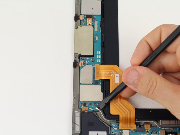
Locate the ribbon running from the midframe and disconnect it from the motherboard with the flat end of a spudger.
-
-
Este paso está sin traducir. Ayuda a traducirlo
-
Use the flat end of the spudger to pop off the connector between the battery and the motherboard.
-
-
Este paso está sin traducir. Ayuda a traducirlo
-
Flip the midframe over and pop the battery out, making sure to slide it out from underneath the ribbon cables.
-
-
Este paso está sin traducir. Ayuda a traducirlo
-
The battery should now be removed and detached from the device.
-
-
Este paso está sin traducir. Ayuda a traducirlo
-
Use the black nylon spudger to lift the gray ZIF connector up and pull out the orange ribbon cable below the camera.
-
-
Este paso está sin traducir. Ayuda a traducirlo
-
Remove the ribbon cable for the front facing camera after popping the red ZIF connector bar up with a spudger.
-
-
Este paso está sin traducir. Ayuda a traducirlo
-
Disconnect the three press fit connectors in the top section of the midframe by prying upwards with the spudger.
-
-
Este paso está sin traducir. Ayuda a traducirlo
-
Pull back the green tape on the upper section of the motherboard with your tweezers to reveal the ZIF connector below.
-
-
Este paso está sin traducir. Ayuda a traducirlo
-
Push the red bar up from the ZIF connector with the spudger and pull the orange, touchpad ribbon cable out.
-
-
Este paso está sin traducir. Ayuda a traducirlo
-
Use the spudger to disconnect five more press fit connectors on the left side of the motherboard by prying upwards.
-
-
Este paso está sin traducir. Ayuda a traducirlo
-
Pop the coaxial antenna cables off from the motherboard with the spudger.
-
-
Este paso está sin traducir. Ayuda a traducirlo
-
Using your fingers, move all the cables aside and wiggle the motherboard free.
-


Cancelar: No complete esta guía.
3 personas más completaron esta guía.

