Esta versión puede contener ediciones incorrectas. Cambie a la última instantánea verificada.
Qué necesitas
-
Este paso está sin traducir. Ayuda a traducirlo
-
Grasp the end of the stylus and remove it from its slot in the midframe.
-
-
Este paso está sin traducir. Ayuda a traducirlo
-
Pry with a plastic opening tool, or your fingernail, in the divot to the left of the rear-facing camera, near the power button.
-
-
Este paso está sin traducir. Ayuda a traducirlo
-
Lift the rear case by the corner nearest the divot and remove it from the phone.
-
-
Este paso está sin traducir. Ayuda a traducirlo
-
If you have an SD card inserted, use the flat end of a spudger, or your fingernail, to press the microSD card slightly deeper into its slot until you hear a click.
-
After the click, release the card and it will pop out of its slot.
-
Remove the microSD card.
-
-
Este paso está sin traducir. Ayuda a traducirlo
-
Insert a plastic opening tool, or your finger, into the notch of the battery compartment and lift the battery upward.
-
-
Este paso está sin traducir. Ayuda a traducirlo
-
Remove the eleven 4.0 mm Phillips #00 screws securing the midframe to the display assembly.
-
-
-
Este paso está sin traducir. Ayuda a traducirlo
-
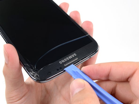
Insert your plastic opening tool between the midframe and front panel assembly on the side of the phone.
-
Slide the plastic opening tool down the seam.
-
-
Este paso está sin traducir. Ayuda a traducirlo
-
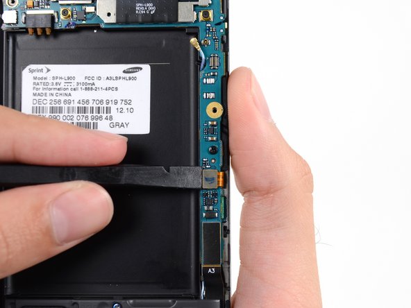
Continue to run the plastic opening tool down the seam.
-
-
Este paso está sin traducir. Ayuda a traducirlo
-
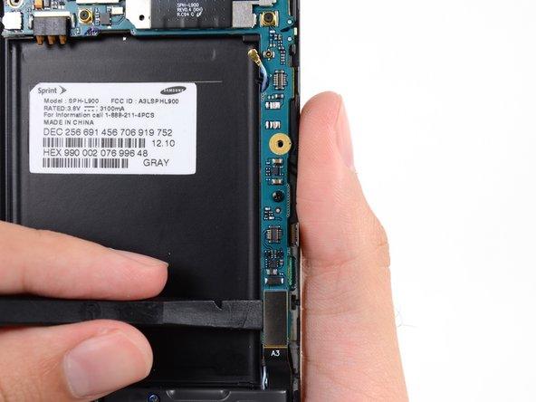
Carefully pry around the corner with a plastic opening tool.
-
-
Este paso está sin traducir. Ayuda a traducirlo
-
Pry along the top of the phone with a plastic opening tool.
-
-
Este paso está sin traducir. Ayuda a traducirlo
-
Push the plastic opening tool down to free the corner of the midframe from the display assembly.
-
-
Este paso está sin traducir. Ayuda a traducirlo
-
Free the clips along the power button side of the phone.
-
Lastly, free the two clips along the top and bottom edge of battery compartment.
-
-
Este paso está sin traducir. Ayuda a traducirlo
-
Use a spudger to disconnect the vibrator/power button assembly cable connector.
-
Disconnect the antenna cable connector.
-
Disconnect the display cable connector.
-
-
Este paso está sin traducir. Ayuda a traducirlo
-
Disconnect the front-facing camera cable connector.
-
Disconnect the headphone jack cable connector.
-
Disconnect the digitizer cable connector.
-
-
Este paso está sin traducir. Ayuda a traducirlo
-
Use the spudger to disconnect the antenna cable connector from the motherboard.
-
Disconnect the soft button cable connector.
-
Disconnect the USB board cable connector.
-
-
Este paso está sin traducir. Ayuda a traducirlo
-
Remove the 3 mm Phillips #00 screw securing the motherboard to the display assembly.
-
-
Este paso está sin traducir. Ayuda a traducirlo
-
Use a spudger to disconnect the rear-facing camera assembly cable connector.
-
-
Este paso está sin traducir. Ayuda a traducirlo
-
Use tweezers, or your fingers, to remove the rear-facing camera assembly.
-


Cancelar: No complete esta guía.
13 personas más completaron esta guía.

