Saltar al contenido principal

Esta versión puede contener ediciones incorrectas. Cambiar a la última instantánea verificada.

Qué necesitas

  1. , Puerta de acceso: paso 1, imagen 1 de 1
    • Afloja el único tronillo Phillips en el contro de la puerta de acceso.

    • Este tornillo es del tipo cautivo en la puerta de acceso.

    • Quita la puerta de acceso de tu iMac.

  2. , Panel de Vidrio: paso 2, imagen 1 de 2 , Panel de Vidrio: paso 2, imagen 2 de 2
    Herramienta utilizada en este paso:
    Heavy-Duty Suction Cups (Pair)
    $14.95
    Comprar
    • El panel de vidrio se fija al bisel frontal con catorce imanes alrededor de su perímetro.

    • Pega dos ventosas en las esquinas opuestas del panel de vidrio.

    • Para colocar las ventosas que vendemos, primero coloca la ventosa con el mango móvil paralelo a la cara del panel de vidrio. Mientras sostienes suavemente la ventosa contra el vidrio, levanta la manija móvil hasta que quede paralela con la otra manija.

    • Si tus ventosas se niegan a adherirse, intenta limpiar tanto el panel de vidrio como la ventosa con un disolvente suave como Windex.

  3. : paso 3, imagen 1 de 1
    • Tira con cuidado del panel de vidrio hacia arriba del iMac.

    • El panel de vidrio tiene varios pines de posicionamiento alrededor de su perímetro. Para evitar cortar estos pasadores del panel de vidrio, asegúrate de tirar solo hacia arriba durante la extracción.

    • Se meticuloso al limpiar la pantalla LCD y la cara interior del panel de vidrio antes de la reinstalación, ya que las huellas dactilares o el polvo atrapado en el interior serán molestamente visibles cuando la pantalla esté encendida.

    • Colocar el vidrio plano, con el interior hacia abajo, sobre una superficie nueva de papel de aluminio es una buena manera de mantenerlo limpio.

  4. , Bisel Frontal: paso 4, imagen 1 de 1
    • Retira los siguientes 12 tornillos que sujetan el bisel frontal a la carcasa trasera:

    • Ocho Torx T8 de 13 mm.

    • Cuatro Torx T8 de 25 mm.

  5. : paso 5, imagen 1 de 1
    • Coloca las manos en las esquinas superiores del bisel (hacia un lado) y levanta el bisel de 2 a 3 cm del cuerpo trabajando desde la parte superior. Después de esto, también puedes desenganchar la parte inferior del bisel (los módulos de memoria evitarán que la parte inferior del bisel se separe primero).

    • Al volver a armar, comienza con la parte inferior del bisel.

    • La parte superior del bisel alberga un micrófono conectado a la placa lógica. Levanta suavemente el bisel para no dañar el cableado o el conector del micrófono tirando accidentalmente del cable.

    • En este punto, puedes desconectar el cable del micrófono y quitar el bisel, o mantener el cable del micrófono conectado y apoyar el bisel en su superficie de trabajo o en el chasis de la Mac.

    • Para separar completamente el bisel: desconecta el conector del cable del micrófono, quitando la cinta según sea necesario.

    • Para mantenerlo conectado, deja el cable del micrófono conectado a la placa lógica y coloca el bisel "sobre" el chasis, con el cable del micrófono formando una bisagra.

    • Si mantienes el micrófono conectado al chasis, asegúrate de no dañar accidentalmente el micrófono o la placa lógica chocando contra el bisel suelto.

  6. : paso 6, imagen 1 de 2 : paso 6, imagen 2 de 2
    • Al volver a montar el bisel:

    • asegúrate de colocar el cable del micrófono y el conector en el espacio vacío junto a la placa de la cámara.

    • Guía con cuidado el conector del micrófono y los cables a través de la ranura de ±1 pulgada de largo a la derecha de la cámara iSight. Una vez que el bisel esté correctamente ensamblado, empuja suavemente el conector del micrófono y el cable dentro del bisel a través de esa ranura.

  7. , Panel de Visualización: paso 7, imagen 1 de 2 , Panel de Visualización: paso 7, imagen 2 de 2
    • Tira del conector del sensor de temperatura LCD hacia arriba para sacarlo de su zócalo en la placa lógica.

    • Si es necesario, desvía el cable del sensor de temperatura LCD de detrás de la placa lógica.

    • Cuando retires la pantalla LCD, verifica el enrutamiento del cable de visualización de temperatura de la pantalla LCD. Al reinstalar la pantalla, asegúrate de que este cable no bloquee uno de los tornillos inferiores del bisel frontal.

  8. : paso 8, imagen 1 de 1
    • Retira los dos tornillos Torx T6 de 5,3 mm que sujetan el cable de visualización de datos a la placa lógica.

  9. : paso 9, imagen 1 de 1
    • Usa la pestaña negra adjunta para sacar el conector del cable de visualización de datos de la placa lógica.

  10. : paso 10, imagen 1 de 2 : paso 10, imagen 2 de 2
    • Retira los ocho tornillos Torx T8 de 12 mm que sujetan el panel de la pantalla a la carcasa trasera.

    • Levanta el panel de la pantalla desde su borde izquierdo y gíralo hacia el borde derecho del iMac.

  11. : paso 11, imagen 1 de 2 : paso 11, imagen 2 de 2
    • Con el panel de visualización aún levantado, desconecta los cuatro cables del inversor.

    • Durante la reinstalación, coloca los cuatro conectores del cable del inversor en los huecos entre los componentes conectados al panel posterior para que el panel de la pantalla quede al ras.

    • Durante el reensamblaje, el orden de los cables del inversor es intercambiable dentro de cada enchufe.

    • Si estás reemplazando un disco duro y tienes un par de manos adicionales, es posible alcanzar y quitar el disco sin desconectar nada más que el conector de pantalla y temperatura de la pantalla LCD en el paso anterior con la pantalla LCD en su posición apoyada.

  12. Este paso está sin traducir. Ayuda a traducirlo

    : paso 12, imagen 1 de 3 : paso 12, imagen 2 de 3 : paso 12, imagen 3 de 3
    • The rest of this procedure should be done in the cleanest possible work environment to avoid dust getting BEHIND the LCD (I learned this the HARD way!)

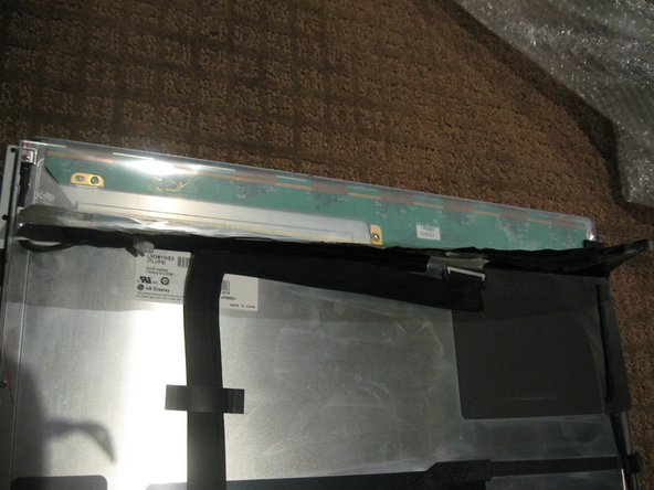
    • Once the LCD panel is removed you need to peel back the black foil from the top edge of the LCD to reveal the clear plastic PCB protector.

    • Now gently peel the clear plastic PCB protector off the top edge. Make sure you don't damage the flex cables attached to the PBC you are exposing.

    • There are a total of 8 flex cables along the top edge

  13. Este paso está sin traducir. Ayuda a traducirlo

    : paso 13, imagen 1 de 3 : paso 13, imagen 2 de 3 : paso 13, imagen 3 de 3
    • Use a sharpie or similar, mark the side brackets on either side of the LCD panel before removing screws as they are different

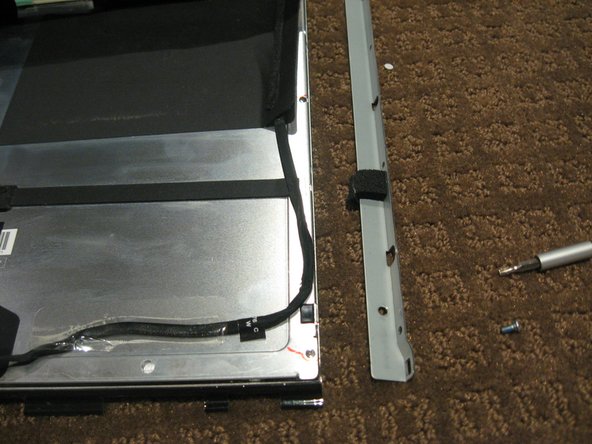
    • Use a T10 Torx driver to remove the 2 screws from each side bracket (total 4 screws)

  14. Este paso está sin traducir. Ayuda a traducirlo

    : paso 14, imagen 1 de 3 : paso 14, imagen 2 de 3 : paso 14, imagen 3 de 3
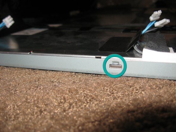
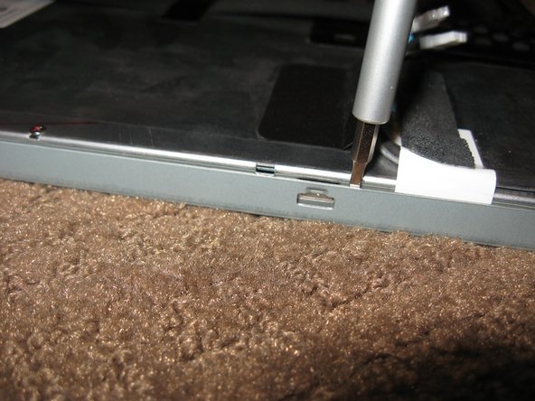
    • Stand the LCD panel on its TOP edge and locate the lock tabs along the BOTTOM edge. There are 5 along the length of the bottom edge

    • Use a flat blade driver or metal spudger to Gently pop the bezel off the lock tabs.

    • Locate the lock tabs on either side of the LCD panel. There are 2 on each side

    • Use a flat blade driver or metal spudger to Gently pop the bezel off the side lock tabs.

  15. Este paso está sin traducir. Ayuda a traducirlo

    : paso 15, imagen 1 de 3 : paso 15, imagen 2 de 3 : paso 15, imagen 3 de 3
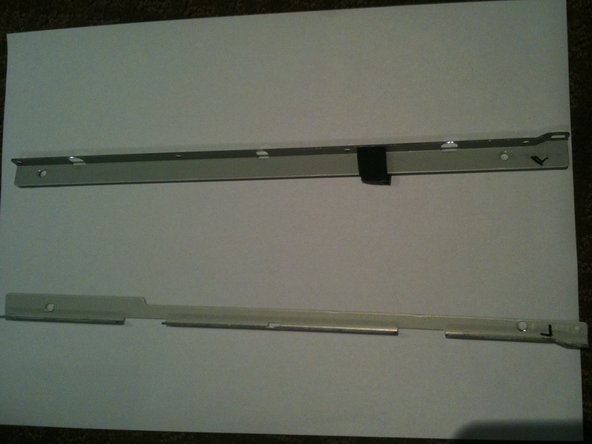
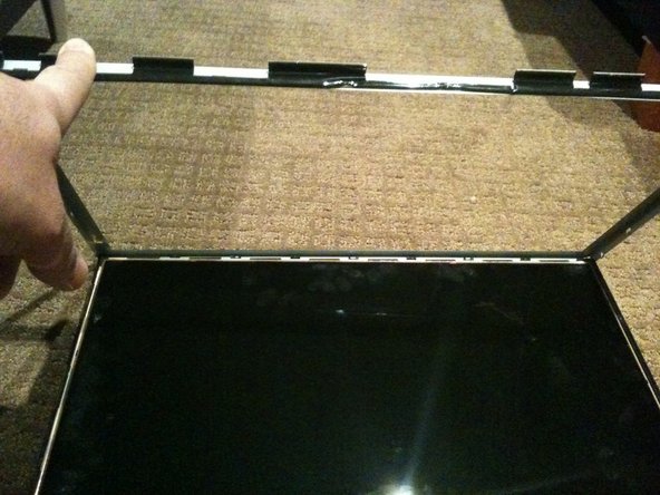
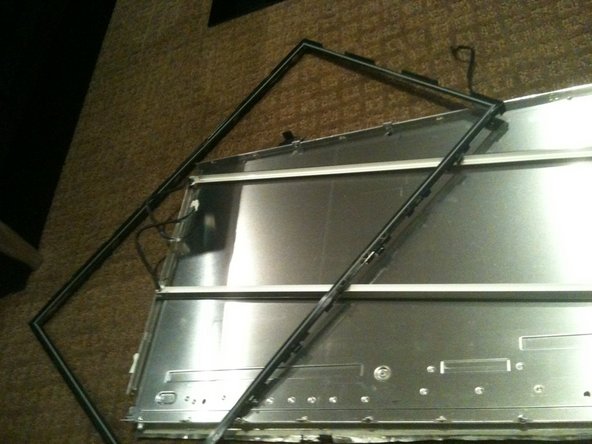
    • Now gently separate the metal bezel from the main body of the LCD panel

    • Lay the LCD panel down on with viewing side UP and remove the metal bezel

    • Make sure you are careful when removing the bezel from the TOP edge as you will be exposing the 8 flex cables mentioned in step 1.

    • Note the 3 flex tabs on the left edge

    • Do not damage any of the tabs or flex cables as these are the Row and Column Drivers. Damage to these will will cause faults like vertical/horizontal lines or white screen etc.

    • WARNING - Once the bezel is removed the LCD is LOOSE in the black plastic frame - only held in by the small gasket underneath.

  16. Este paso está sin traducir. Ayuda a traducirlo

    : paso 16, imagen 1 de 2 : paso 16, imagen 2 de 2
    • Using a plastic spudger or pry tool, work GENTLY around the edges of the LCD to loosen it from the gasket below - use GREAT CARE so you don't crack or chip the panel as it is only a couple mm thick

    • Once the LCD is loose you need to HOLD it in place in the black plastic frame and GENTLY flip the entire assembly so the LCD is flat on the work surface

  17. Este paso está sin traducir. Ayuda a traducirlo

    : paso 17, imagen 1 de 2 : paso 17, imagen 2 de 2
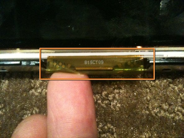
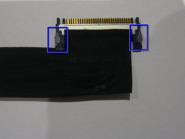
    • Remove the tape securing the LVDS cable

    • Press IN the 2 silver spring loaded catches on either side to release the cable and gently extract it from the connector

  18. Este paso está sin traducir. Ayuda a traducirlo

    : paso 18, imagen 1 de 2 : paso 18, imagen 2 de 2
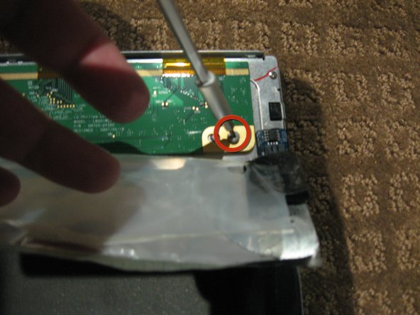
    • Peel the back Black foil and clear plastic PCB protector to fully expose the PCB that runs across the top of the LCD assembly

    • Remove the 2ea Philips head screws from each end of the PCB

    • The PCB actually has a 3rd screw hole in the centre of the board. Perhaps my assembly is missing a screw

  19. Este paso está sin traducir. Ayuda a traducirlo

    : paso 19, imagen 1 de 2 : paso 19, imagen 2 de 2
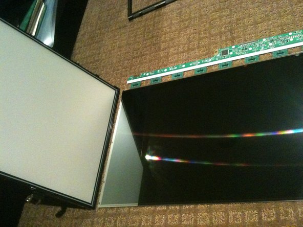
    • Gently flip the PCB over 180deg so it is off the aluminum back panel.

    • Be CAREFUL not to damage the 8 flex cables

    • The PCB may be attached to the aluminium by some adhesive near the LVDS connector. IF so use a plastic pry tool or spudger to GENTLY lift the PCB up

    • Now lift the the back panel off the LCD separating the LCD from the back light assembly

  20. Este paso está sin traducir. Ayuda a traducirlo

    : paso 20, imagen 1 de 3 : paso 20, imagen 2 de 3 : paso 20, imagen 3 de 3
    • Disassembling the back-light assembly is a little fiddly as there are a number of parts that all want to come apart at the same time

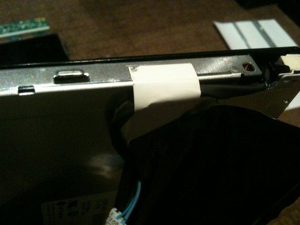
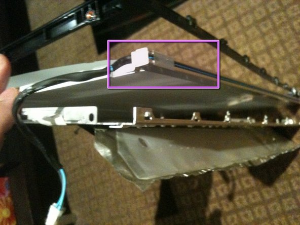
    • Remove the 6 Philips screws from the rear of the back light assembly

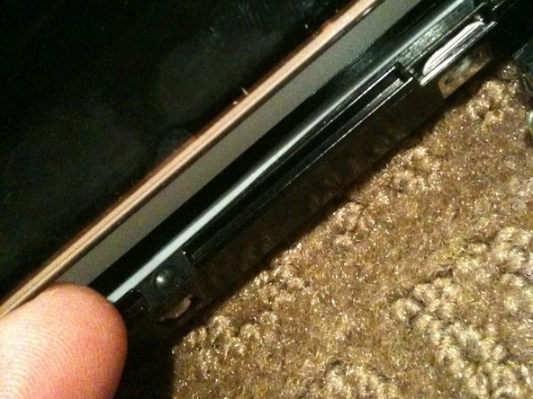
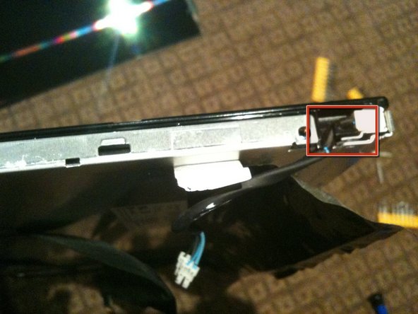
    • Removing the white tape from the CCFL cable.

    • Un-clip the CCFL cable from the black plastic surround

    • There are 2 CCFL cables and the process is essentially the same for each

  21. Este paso está sin traducir. Ayuda a traducirlo

    : paso 21, imagen 1 de 3 : paso 21, imagen 2 de 3 : paso 21, imagen 3 de 3
    • Separate the black plastic surround from the aluminum back plate to access the CCFL tube assemblies

    • Start by un-clipping the tabs along the top edge of the assembly. There are 4 tabs along the top

    • The top CCFL tube can be seen and CAREFULLY removed

  22. Este paso está sin traducir. Ayuda a traducirlo

    : paso 22, imagen 1 de 3 : paso 22, imagen 2 de 3 : paso 22, imagen 3 de 3
    • The bottom of the black surround can now be un-clipped and the entire surround removed

    • There are 4 tabs along the bottom of the assembly

    • Once the black surround is off the rest pretty much comes apart with the bottom CCFL tube being able to be removed in a similar manner to the top

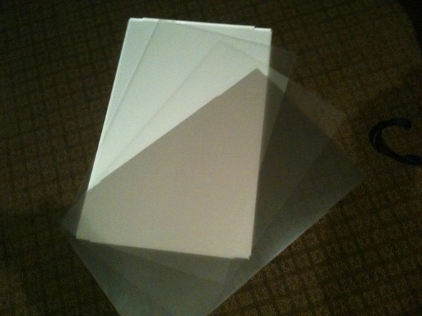
    • The centre of the back light assembly is made up of 4 main parts. A perspex sheet with white plastic coating, 2 opaque matt plastic sheets, and 1 Pearlescent matt plastic sheet

    • The plastic sheets are polarisers so need to be kept clean and free of dust and scratches

  23. Este paso está sin traducir. Ayuda a traducirlo

    : paso 23, imagen 1 de 3 : paso 23, imagen 2 de 3 : paso 23, imagen 3 de 3
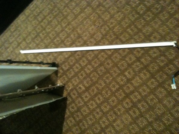
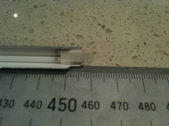
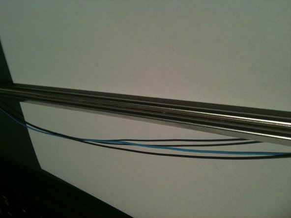
    • The CCLF tube assemblies are made up of a U shaped reflector with 2ea individual tubes inside. The entire assembly is 457mm long and 7.6mm wide. There are no part numbers on the assembly however there is a S on the end with the wires attached and an 18 on the other end.

    • The 2 CCFL tubes are held together with a figure 8 rubber band in the middle of the reflector so both tubes must come out at the same time.

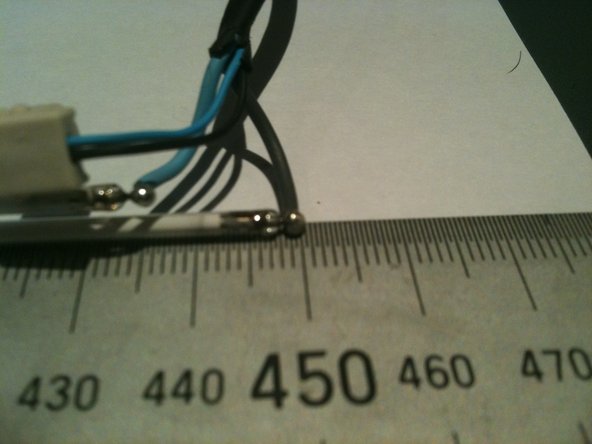
    • The individual tubes are 448mm long (excluding the terminals - standard way to measure is end of glass to end of glass) and are 2.4mm diameter.

    • The CCFL are soldered to the wires so not a simple plug in replacement

    • The CCFL are EXTREMELY fragile so ensure you dont break them when installing them.

    • The CCFL reflectors are a tight fit over the sides of the perspex sheet and the other layers of plastic. Patience and a plastic spudger or pry tool should get you there

    • The closest I can find to my CCFL measurements are either the 446mm x 2.4mm or the 450mm x 2.4mm so I'd suggest the 446mm is used

    • See the Removing CCFL from iMac 20in LCD CCFL assembly guide for details

  24. Este paso está sin traducir. Ayuda a traducirlo

    : paso 24, imagen 1 de 3 : paso 24, imagen 2 de 3 : paso 24, imagen 3 de 3
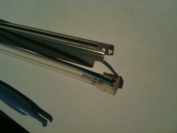
    • Remove the white tape from either end of the rear of the CCFL assembly.

    • Carefully remove about 15-20mm of heat shrink from the CCFL cable to allow the end cap to be removed, making sure you DO NOT cut or nick the wire insulation.

    • The wires have a HIGH VOLTAGE applied during operation and the insulation may break down if damaged causing a short

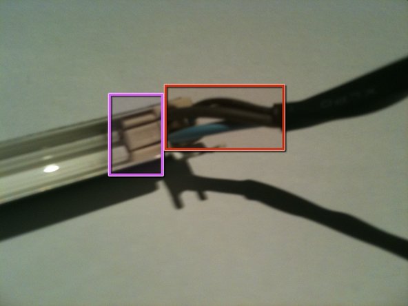
    • While holding the assembly, slowly and gently pull the THICK wires up and out of the slots in the white rubber cap.

    • Pull the wires one at a time ensuring you don't flex the CCFL and break it.

    • This will reveal the pins and solder joints.

  25. Este paso está sin traducir. Ayuda a traducirlo

    : paso 25, imagen 1 de 3 : paso 25, imagen 2 de 3 : paso 25, imagen 3 de 3
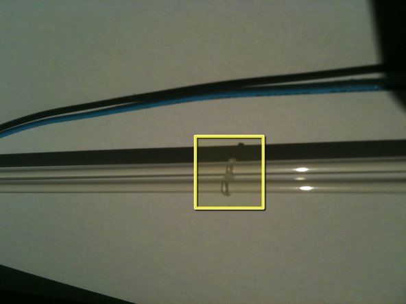
    • Gently push the THIN wires through the rubber end cap to create a bit of a loop on the rear of the assembly.

    • Using a plastic pry tool you can pop the rubber end cap out and then lift the thin wires out of the groove in the rear of the CCFL assembly

    • Note the thin wires are held in the groove by a small amount of adhesive.

    • Run the pry tool the length of the assembly and free the wires all the way to the other end cap

    • gently pop the rubber end cap out of the assembly

  26. Este paso está sin traducir. Ayuda a traducirlo

    : paso 26, imagen 1 de 3 : paso 26, imagen 2 de 3 : paso 26, imagen 3 de 3
    • Gently pull the rubber end cap off the CCFL to expose the pins and solder joints

    • The CCFL are FRAGILE and will easily break

    • Now its a simple task of un-soldering each wire and soldering in the new CCFL

    • There is a little figure 8 rubber band tying the 2 CCFL together at their centre.

Linea de Meta

5 personas más completaron esta guía.

Richdave

Miembro Desde 04/09/10

32,063 Reputación

30 Guías creadas

Equipo

Master Techs Miembro de Master Techs

Community

322 Miembros

2,532 Guías creadas

Un comentario

Anyone swapped out the ccfl for leds?

Dan - Contestar

Agregar Comentario

Ver Estadísticas:

Ultimas 24 horas: 2

Ultimos 7 días: 7

Ultimos 30 días: 24

Todo El Tiempo: 15,823