Esta traducción podría no reflejar los cambios más recientes añadidos a la guía de referencia. Ayúdanos a actualizar la traducción o revisa la guía original.
Introducción
Utiliza esta guía para reemplazar la placa lógica.
La eliminación de la placa lógica significa que necesitarás [guía|744|volver a aplicar una capa de compuesto térmico].
Antes de comenzar cualquier trabajo en su Mac Pro: Desenchufa la computadora y mantén pulsado el botón de encendido durante diez segundos para descargar los capacitores de la fuente de alimentación.
Ten mucho cuidado de no tocar los conductores de capacitores o cualquier junta de soldadura expuesta en la parte posterior de la fuente de alimentación. Solo maneja el tablero por los bordes.
Qué necesitas
-
-
Desliza el interruptor de bloqueo hacia la derecha, hasta la posición de desbloqueo.
-
-
-
Quita los cinco tornillos Torx T10 de 5.1 mm de todo el perímetro exterior del ensamblaje del ventilador.
Fat Mango is correct. That said. If you do pull the fan assembly note that the screws are all held in with blue Permatex and breaking them free takes a fair amount of effort. Getting a good set of Torx screwdrivers is a must.
Hey guys, what would happen if you only replace one card.. I have a D300 but the plan is to upgrade to D500 or D600. So If I can afford and install one instead of the pair would it increase something? or will it cause any conflict? I guess I don’t understand if I the Mac Pro has 2 D300 graphic cards that means each has 1GB? Same as If I would Install 1 D600 that would increase 3GB only? Thanks.
D300 = 2GB each card. Very few apps uses two cards at the same time.
Gio Cas -
The (5) Screws are Apple part number 923-0713
-
-
-
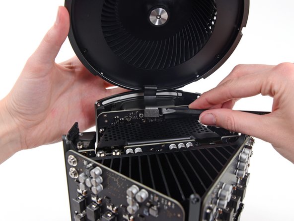
Mientras sostienes el ensamblaje del ventilador con una mano, afloja los dos tornillos cautivos T8 en el soporte del cable del ventilador.
On my machine, a TR7 worked to remove them due to the weird angle.
-
-
-
Retira los cinco tornillos Torx T10 de 5.1 mm del perímetro exterior de la caja inferior.
-
-
-
-
Utiliza el extremo plano de un spudger y un movimiento de giro para separar suavemente un lado de la conexión de datos de la tarjeta gráfica.
-
-
-
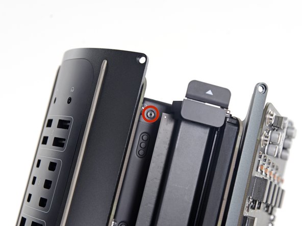
Retira los dos tornillos Torx T7 de 6,0 mm que sujetan la placa de interconexión al disipador de calor.
Ended up being T9 screws for me.
T8 screws for me, i did and edit to this step
Ended up being T15 screws on my machine
-
-
-
Da la vuelta al Mac Pro y colócalo suavemente sobre una superficie plana.
-
-
-
Retira los dos tornillos Torx T8 de 5.5 mm.
Step 22 when reassembling, it helps not to fully tighten until you put the screws in from step 20.
-
-
-
Retira los cuatro tornillos Torx T10 de 12,8 mm del soporte del disipador de calor de la CPU.
I cannot unscrew one of those because I appears that one of the elements in wich it is screwd underneath is loose and moving along with the screw, making this operation impossible. Anyone had this issue ?? Any solution ??
I had the same problem. These screws go into threaded inserts, which in turn are screwed into the heatsink. Both have threadlocker compound applied. So the threaded insert’s threadlocker gives up first, and the threaded insert unscrews from the heatsink. Remove all 4 screws, then with a pair of needle nose pliers, hemostat, or thin 7mm wrench, hold the insert steady and unscrew the screw from it.
Could I remove these screws and re-screw? I worry that remove them but I can’t re-use them?
timmy123 -
I had that problem, too, and I did it like Chuck Fry, with a thin wrench. Unfortunately one threaded insert was so tight that I slipped and a capacitor broke off. Can someone tell me what kind of capacitor I need? I can't find anything under the name listed above the capacitor. Thank you.
A way to avoid this situation is to ease the tension on the spring slowly and rotate the loosening of four screws a few turns at a time – when the tension is released equally the threaded inserts are more likely to stay in place.
I had 2 of those double sided screws stuck like that. I carefully removed them from the motherboard using a small vice grip to hold one side, and a torx on the other. Then reinstalled them using locktite compound. Make sure the heat sink is flush to the motherboard in the same way that you found it, or the assembly will not fit back in the case correctly, indicating the CPU may not be securely attached. The result may be that you think you killed your mac when you turn in on again and just hear the fan spinning like crazy but no chime or boot sequence. If that happens, go back in, reset the double sided screws, and make sure the heatsink is flush. Worked for me.
-
-
-
Retira los cuatro tornillos internos Torx T10 de 12.8 mm del soporte del disipador de calor de la CPU.
-
Retira el soporte del disipador de calor de la CPU.
On my Mac Pro (assembled mid-2017) these screws are covered with a black sticker presumably to indicate tampering. If you did not know they were screws it would not be obvious. You have to just put the T10 driver right in the center and start turning; it quickly breaks through the sticker.
Oh man. Thanks so much for that comment! I would have tried to use pliers!
Also remember to support the CPU (On the other side) while removing these screws. Mine CPU fell out from the other side while loosening.
On my MacPro there are no screws here. On the backside the place where the back of the screws should be are covered with stickers, but removing the stickers simply reveals a rivet. There’s no screw and seemingly no way to remove the CPU.
Wow, glad I clicked comments. I had no clue about the sticker. I was about to use some kind of something to get them out 😂
-
-
-
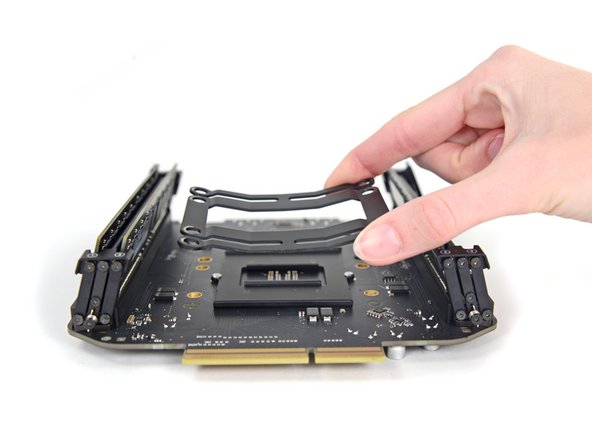
Levanta y retira la placa lógica de la CPU y el soporte.
-
Durante el reensamble, asegúrate de limpiar y reemplazar el compuesto térmico en la CPU.
-
Tenemos una guía de pasta térmica que facilita el reemplazo del compuesto térmico.
There is one import piece of information when replacing or upgrading these processors. There are two possible orientations and only one is correct (correct me if I’m wrong!). There’s a small arrow on one corner of the processor that needs to be aligned to the correct side. Just match the orientation of the original processor - this can be difficult or easy to overlook since the tiny alignment arrow is usually covered with thermal paste. Clean the Thermal paste off the old processor before you remove it to see the correct alignment.
-


Para volver a ensamblar tu dispositivo, sigue estas instrucciones en orden inverso
Para volver a ensamblar tu dispositivo, sigue estas instrucciones en orden inverso
Cancelar: No complete esta guía.
11 personas más completaron esta guía.
Un agradecimiento especial a estos traductores:
90%


Estos traductores nos están ayudando a reparar el mundo! ¿Quieres contribuir?
Empezar a traducir ›

Un comentario
The RAM/CPU board is only attached to the thermal core around the processor area. This means seating RAM modules can flex the board (which has no support under the RAM sockets) so take extra care seating RAM modules.