Saltar al contenido principal

RIDGID R32104 Motor Rotor Replacement

Qué necesitas

  1. RIDGID R32104 Motor Rotor Replacement, Motor Brush: paso 1, imagen 1 de 2 RIDGID R32104 Motor Rotor Replacement, Motor Brush: paso 1, imagen 2 de 2
    • Turn off your saw and unplug before starting.

    • Place down the Worm Drive Saw on a sturdy surface.

    • The motor brush cap is located on the side of the main housing assembly, it can be identified as a large black plastic cap with a slit running down its surface.

  2. RIDGID R32104 Motor Rotor Replacement: paso 2, imagen 1 de 2 RIDGID R32104 Motor Rotor Replacement: paso 2, imagen 2 de 2
    • Using a flathead screwdriver, remove the motor brush cap from the main housing assembly.

  3. RIDGID R32104 Motor Rotor Replacement: paso 3, imagen 1 de 1
    • With the cap removed, the motor brush should now be accessible.

    • Carefully remove the motor brush by sliding it out of the main housing assembly.

  4. RIDGID R32104 Motor Rotor Replacement, Upper Blade Guard Assembly: paso 4, imagen 1 de 3 RIDGID R32104 Motor Rotor Replacement, Upper Blade Guard Assembly: paso 4, imagen 2 de 3 RIDGID R32104 Motor Rotor Replacement, Upper Blade Guard Assembly: paso 4, imagen 3 de 3
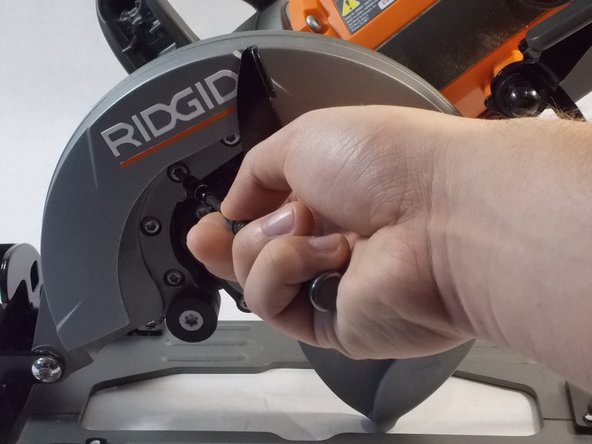
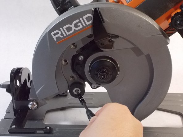
    • Maneuver the RIDGID saw, in order to easily remove the upper blade guard assembly.

    • Using the T20 Torx Screwdriver, remove the four 4/10 cm screws that attach to the gear box.

  5. RIDGID R32104 Motor Rotor Replacement: paso 5, imagen 1 de 2 RIDGID R32104 Motor Rotor Replacement: paso 5, imagen 2 de 2
    • Using the T50 Torx Screwdriver, remove the one 5/10 screw that attach to the gear box.

  6. RIDGID R32104 Motor Rotor Replacement: paso 6, imagen 1 de 2 RIDGID R32104 Motor Rotor Replacement: paso 6, imagen 2 de 2
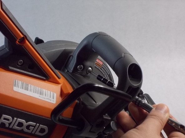
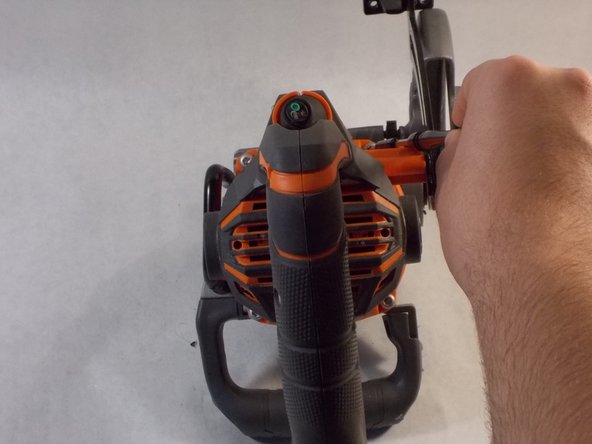
    • Using the T20 Torx Screwdriver, remove the two 4/10 cm screws that attach to the handle of the device.

  7. RIDGID R32104 Motor Rotor Replacement: paso 7, imagen 1 de 2 RIDGID R32104 Motor Rotor Replacement: paso 7, imagen 2 de 2
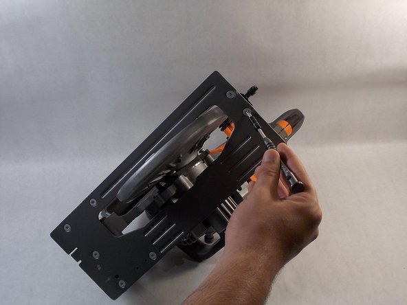
    • Maneuver the saw to get to the base plate.

    • Using the T20 Torx Screwdriver, remove the two 4/10 cm screws that attach the upper blade guard’s base plate to the main housing assembly.

  8. RIDGID R32104 Motor Rotor Replacement, Main Housing Assembly: paso 8, imagen 1 de 2 RIDGID R32104 Motor Rotor Replacement, Main Housing Assembly: paso 8, imagen 2 de 2
    • Using the T20 Torx Screwdriver, remove the four 10 cm screws that attaches the main housing assembly to the gear box.

  9. RIDGID R32104 Motor Rotor Replacement, Gear Box: paso 9, imagen 1 de 2 RIDGID R32104 Motor Rotor Replacement, Gear Box: paso 9, imagen 2 de 2
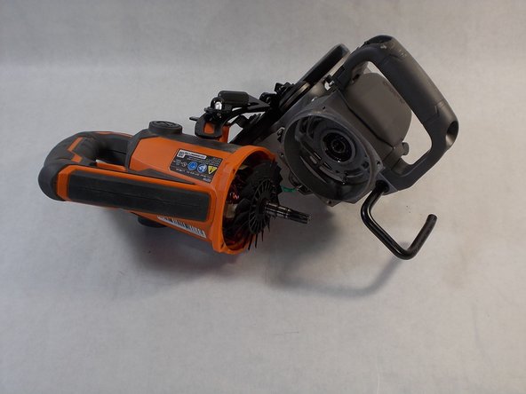
    • Wiggle out the gear box to easily gain access to the motor rotor.

    • Once taken out, the motor rotor is easily accessible.

  10. RIDGID R32104 Motor Rotor Replacement, Motor Rotor: paso 10, imagen 1 de 3 RIDGID R32104 Motor Rotor Replacement, Motor Rotor: paso 10, imagen 2 de 3 RIDGID R32104 Motor Rotor Replacement, Motor Rotor: paso 10, imagen 3 de 3
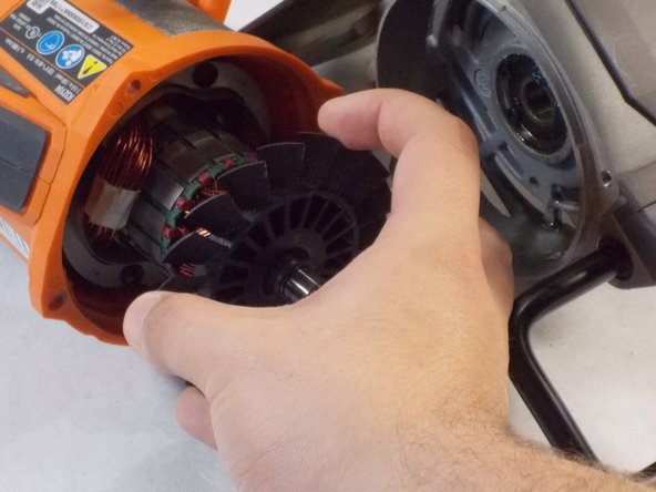
    • The motor rotor is lodged in between the armature and can be identified as a rod containing a fan blade.

    • Carefully remove the motor rotor from the device.

Conclusión

To reassemble your device, follow these instructions in reverse order.

Una persona más ha completado esta guía.

Lucas Pimentel

Miembro Desde 04/02/19

1,010 Reputación

8 Guías creadas

Equipo

0 comentarios

Agregar Comentario

Ver Estadísticas:

Ultimas 24 horas: 0

Ultimos 7 días: 0

Ultimos 30 días: 5

Todo El Tiempo: 462