Esta versión puede contener ediciones incorrectas. Cambie a la última instantánea verificada.
Qué necesitas
-
Este paso está sin traducir. Ayuda a traducirlo
-
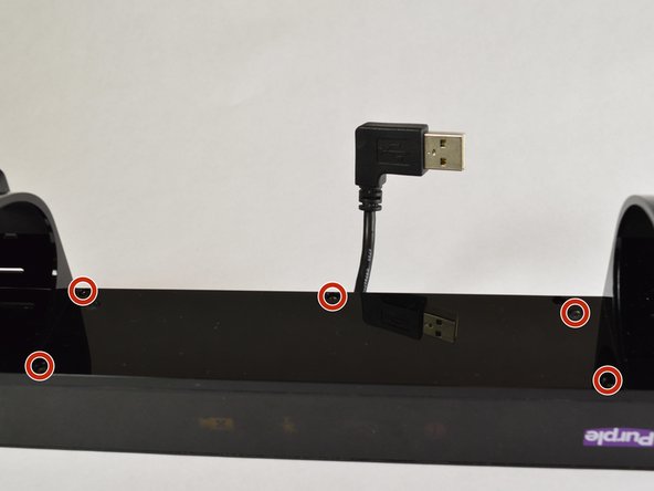
Remove the top bar by removing the 5cm hex T10 screws on the back of the device as shown. Then gently pull off the top bar from the main component.
-
-
Este paso está sin traducir. Ayuda a traducirlo
-
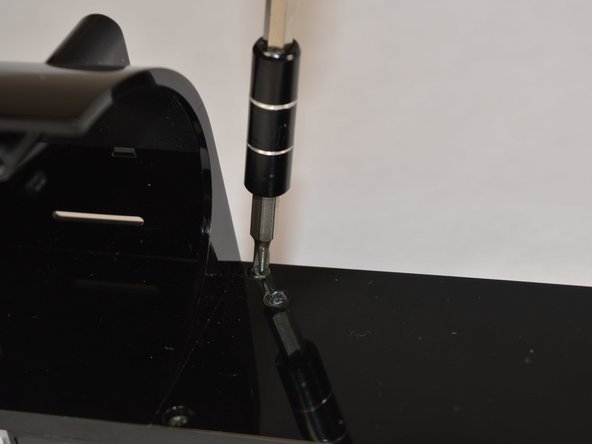
Remove the 1.2 cm hex T9 screws and gently open up the device.
-
-
Este paso está sin traducir. Ayuda a traducirlo
-
Flip the top bar over and using a #00 phillips head screwdriver, remove the five 7mm screws holding the bar together.
-
-
-
Este paso está sin traducir. Ayuda a traducirlo
-
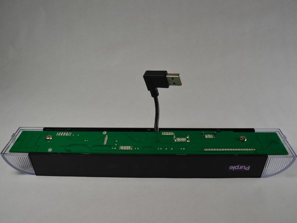
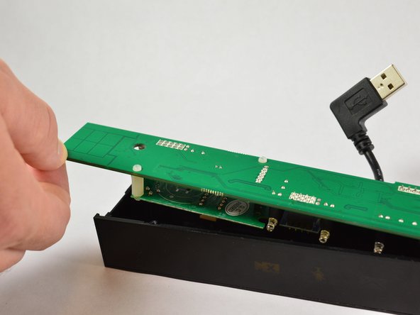
Carefully pry off the plastic panel, revealing the motherboard.
-
-
Este paso está sin traducir. Ayuda a traducirlo
-
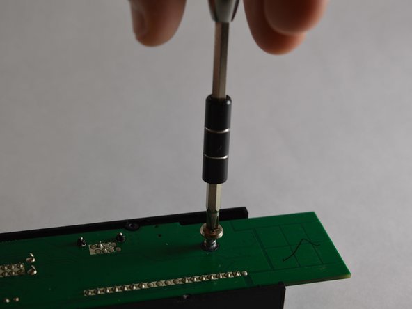
Remove the two 7mm screws holding the motherboard in place with a phillips head screwdriver size #00.
-
-
Este paso está sin traducir. Ayuda a traducirlo
-
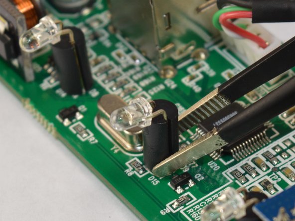
To release the motherboard from its plastic housing, first pull the plastic light covers up and away from the device.
-
-
Este paso está sin traducir. Ayuda a traducirlo
-
Heat the solder on the underside of the affected light to remove and replace it using tweezers.
-


Equipo

Appalachian State University, Team S2-G6, Menagarishvili Fall 2018 Miembro de Appalachian State University, Team S2-G6, Menagarishvili Fall 2018
APSU-MENAGARISHVILI-F18S2G6
3 Miembros
4 Guías creadas