Introducción
The Terracopter EVO controller motherboard is used to control all of the functions of the controller and relay them to the drone.
Qué necesitas
-
-
Using a Phillips #0 screwdriver, remove the screw connecting the battery cover to the controller.
-
Remove the battery cover from the controller.
-
-
Paso 3 Protocol TerraCopter EVO Controller Opening
Aviso: los pasos 3-4 provienen de una guía que está marcada como "En progreso".
-
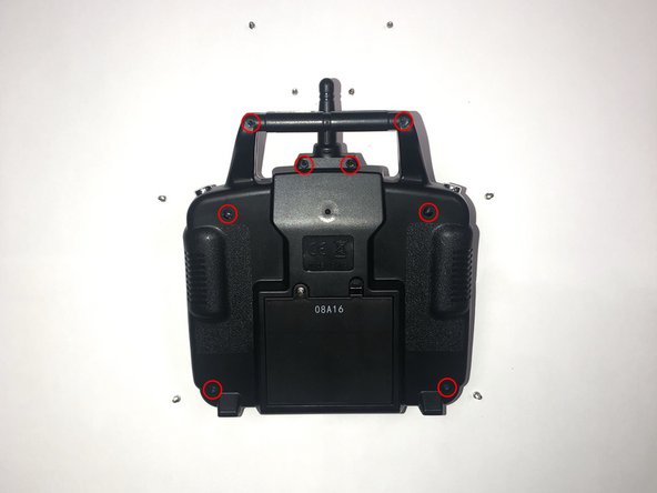
Orientate the controller to where the battery compartment is facing upwards.
-
Remove the four 5mm and four 4mm Phillips #1 screws from the case.
-
-
-
-
Locate the single pin holding the negative and positive wires to the motherboard. Each lead should have one pin holding each wire to the green side of the motherboard.
-
Using a soldering iron, melt the existing solder point for the red lead (positive line).
-
Using a soldering iron, melt the existing solder point for the black lead (negative line).
-
Pull the red and black leads through their respective holes, out of the motherboard.
-


To reassemble your device, follow these instructions in reverse order.
To reassemble your device, follow these instructions in reverse order.
Cancelar: No complete esta guía.
Una persona más ha completado esta guía.
Equipo

The Citadel Military College of South Carolina, Team S1-G22, Eggleston Fall 2019 Miembro de The Citadel Military College of South Carolina, Team S1-G22, Eggleston Fall 2019
CMCSC-EGGLESTON-F19S1G22
3 Miembros
3 Guías creadas