Esta versión puede contener ediciones incorrectas. Cambiar a la última instantánea verificada.
Qué necesitas
-
-
Usa una moneda para rodar el tornillo bloqueador de la batería 90 grados, en el sentido de las agujas del reloj.
-
Saca la batería de la computadora.
-
-
-
Saca los 10 tornillos siguientes:
-
Dos tornillos Phillips de 3 mm, del compartimento da la batería, en ambos los lados de los contactos de la batería.
-
Cuatro tornillos Philips de 3 mm, alrededor del compartimento de la memoria.
-
Cuatro tornillos Phillips de 16 mm, al lo largo de la bisagra.
-
-
-
Gira la computadora 90 grados en el sentido de las agujas del reloj, de forma que los puertos estén orientados hacia ti.
-
Saca los tres tornillos Phillips de 3 mm, a lo largo del borde de la caja inferior.
-
Cuando sustituyas estos tornillos, deberás instalarlos en la orden correcta. Empieza por el más cercano de la bisagra de la pantalla y sigue en dirección a la parte delantera del ordenador. Ten cuidado para no ponerlos en los dos agujeros de los lados del puerto de la salida de vídeo.
-
-
-
-
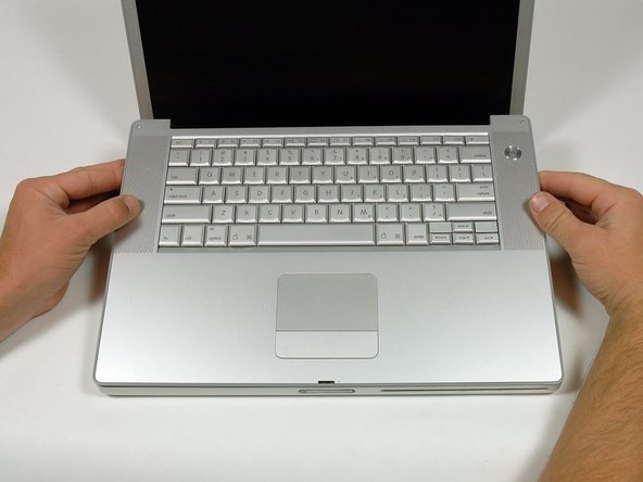
Sujeta las esquinas traseras de la caja superior y tira hacia arriba.
-
Levanta la parte posterior de la caja y trabaja con los dedos a los lados, liberando la caja a medida que avanzas. Una vez que hayas liberado los lados, es posible que debas mover la caja hacia arriba y hacia abajo para liberar el frente de la caja superior.
-
-
Este paso está sin traducir. Ayuda a traducirlo
-
Remove the 12 mm Phillips screw holding the right speaker assembly to the lower case.
-
-
Este paso está sin traducir. Ayuda a traducirlo
-
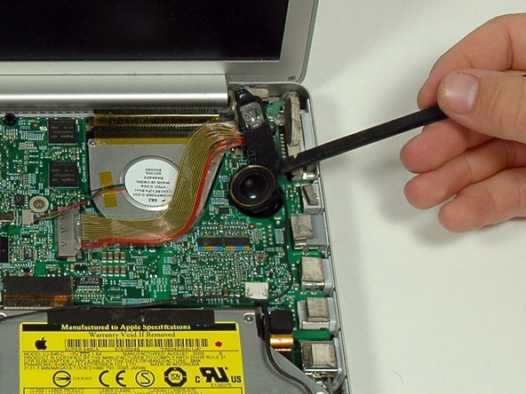
Use a spudger to gently pry the speaker out of its housing.
-
-
Este paso está sin traducir. Ayuda a traducirlo
-
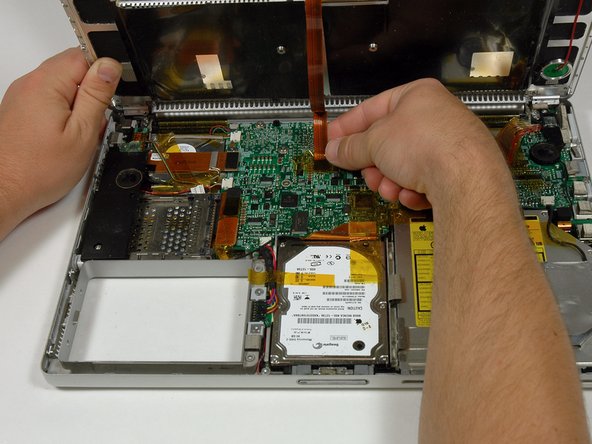
Disconnect the hard drive and optical drive connectors from the logic board.
-
Disconnect the right speaker cable connector.
-
De-route the right speaker cable and remove the speaker from the computer.
-
-
Este paso está sin traducir. Ayuda a traducirlo
-
Disconnect the 11 remaining cable connectors, removing tape as necessary.
-
-
Este paso está sin traducir. Ayuda a traducirlo
-
Remove the following 9 Phillips screws from the logic board:
-
Three 6.5 mm in the upper left corner.
-
Six remaining 4.5 mm.
-
-
Este paso está sin traducir. Ayuda a traducirlo
-
Lift up the left side of the logic board enough to disconnect the black and red power cable from the left side of the logic board.
-
While the logic board is lifted, also disconnect the battery connector.
-
-
Este paso está sin traducir. Ayuda a traducirlo
-
Remove the single black Phillips screw from the top of the left speaker housing.
-
Remove the 4 mm hex nut from the left speaker housing.
-
Lift the left speaker housing from the lower case and disconnect the microphone/speaker connector.
-
-
Este paso está sin traducir. Ayuda a traducirlo
-
Lift the left side of the logic board and disconnect the modem cable from the underside of the logic board. A spudger is useful for freeing the connector from its adhesive.
-
-
Este paso está sin traducir. Ayuda a traducirlo
-
Very gently lift up the left side of the logic board.
-
Lift the left edge of the board up to approximately a 30 degree angle (if you don't have your protractor handy, just lift until the DVI port clears the right hinge).
-
Once the logic board clears the ports, slide it out to the left.
-
-
Este paso está sin traducir. Ayuda a traducirlo
-
Use a firm plastic edge to scrape the thermal material off the heat sink.
-
Apply a new layer of thermal paste to the heat sink.
-


Cancelar: No complete esta guía.
15 personas más completaron esta guía.
