Esta versión puede contener ediciones incorrectas. Cambiar a la última instantánea verificada.
Qué necesitas
-
-
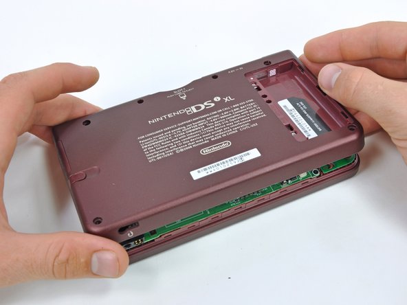
Retira los dos tornillos Phillips que fijan la tapa de la batería a la parte posterior de la consola portátil.
-
Quita la tapa de la batería de la parte posterior de la DSi XL.
-
-
Este paso está sin traducir. Ayuda a traducirlo
-
Remove the four rubber screw covers on the lower case by prying them up with a push pin.
-
-
Este paso está sin traducir. Ayuda a traducirlo
-
Remove the following seven Phillips screws that secure the lower case to the rest of the DSi XL:
-
Four silver 5.3 mm screws
-
Two black 5.3 mm screws
-
One black 2.5 mm screw
-
-
Este paso está sin traducir. Ayuda a traducirlo
-
Insert a spudger between the upper and lower case at the bottom left corner of the DSi.
-
Slide the spudger along the bottom edge of the upper case to release the latches securing the upper case to the lower case.
-
-
Este paso está sin traducir. Ayuda a traducirlo
-
Lift the lower case from the front edge.
-
Rotate the lower case away from the DSi.
-
-
Este paso está sin traducir. Ayuda a traducirlo
-
Using a spudger, pry the SD card/right shoulder button connector off its socket.
-
Pry the volume button/left shoulder button connector off its socket on the motherboard with a spudger.
-
-
Este paso está sin traducir. Ayuda a traducirlo
-
Lift the Wi-Fi board up off its socket on the motherboard.
-
-
Este paso está sin traducir. Ayuda a traducirlo
-
Use a spudger to pry the microphone cable off the motherboard.
-
-
Este paso está sin traducir. Ayuda a traducirlo
-
Using the flat end of a spudger, flip up the retaining flap on the camera ribbon ZIF connector.
-
Use the pointed end of a spudger to pull the camera ribbon from the ZIF connector.
-
-
Este paso está sin traducir. Ayuda a traducirlo
-
Using the flat end of a spudger, flip up the retaining flap on the touchscreen cable ZIF connector.
-
With the pointed end of the spudger, pull the touchscreen cable from its connector on the motherboard.
-
-
Este paso está sin traducir. Ayuda a traducirlo
-
Using the flat end of a spudger, flip up the retaining flap on the backlight cable ZIF connector.
-
With the pointed end of the spudger, pull the backlight cable from its connector on the motherboard.
-
-
Este paso está sin traducir. Ayuda a traducirlo
-
Using the flat end of a spudger, flip up the retaining flap on the lower display data cable ZIF connector.
-
With the pointed end of the spudger, pull the lower display data cable from its connector on the motherboard.
-
-
Este paso está sin traducir. Ayuda a traducirlo
-
Using the flat end of a spudger, flip up the retaining flap on the ZIF connector for the D-Pad/power button cable.
-
With the pointed end of the spudger, pull the D-Pad/power button cable from its connector on the motherboard.
-
-
-
Este paso está sin traducir. Ayuda a traducirlo
-
Using the flat end of the spudger, pry the battery cable up off its socket on the motherboard.
-
-
Este paso está sin traducir. Ayuda a traducirlo
-
Remove the screws securing the motherboard to the upper case:
-
A single 2.5 mm silver Phillips screw
-
Four 3.7 mm black Phillips screws
-
-
Este paso está sin traducir. Ayuda a traducirlo
-
Deroute the microphone and antenna cables through the slot in the motherboard.
-
-
Este paso está sin traducir. Ayuda a traducirlo
-
Using the flat end of a spudger, flip up the retaining flap on the upper display data cable ZIF connector.
-
With the pointed end of the spudger, pull the upper display data cable from its connector on the underside of the motherboard.
-
-
Este paso está sin traducir. Ayuda a traducirlo
-
Turn the DSi XL over and open the display.
-
Use a pushpin to remove the four plastic screw covers on the front bezel.
-
-
Este paso está sin traducir. Ayuda a traducirlo
-
Remove the four 3.5 mm silver Phillips screws securing the rear bezel to the front bezel.
-
-
Este paso está sin traducir. Ayuda a traducirlo
-
Using two hands, gently slide the rear bezel upwards.
-
-
Este paso está sin traducir. Ayuda a traducirlo
-
Insert a spudger into the gap between the front and rear bezel.
-
Rotate the spudger away from the DSi XL, prying the two bezels apart.
-
-
Este paso está sin traducir. Ayuda a traducirlo
-
In the same manner as described above, continue prying along the top edge of the front and rear bezels.
-
-
Este paso está sin traducir. Ayuda a traducirlo
-
Using the flat end of a spudger, pry the rear camera off the rear bezel.
-
Remove the rear bezel.
-
-
Este paso está sin traducir. Ayuda a traducirlo
-
Using a pair of tweezers, pull the microphone out of its housing in the front bezel.
-
De-route the microphone cable, and pull it through the right hinge.
-
-
Este paso está sin traducir. Ayuda a traducirlo
-
Using the flat end of a spudger, pry the left speaker out of its socket on the front bezel.
-
De-route the speaker cable along the top edge of the screen.
-
In the same manner described above, remove the right speaker from its socket on the front bezel.
-
Place both speakers on the back of the upper LCD.
-
-
Este paso está sin traducir. Ayuda a traducirlo
-
Remove the seven 2.5 mm silver screws securing the power board to the upper case.
-
Lift the power board up off the upper case.
-
-
Este paso está sin traducir. Ayuda a traducirlo
-
Peel the rubber button pads off the backside of the D-pad and power button.
-
-
Este paso está sin traducir. Ayuda a traducirlo
-
Push the D-pad up through its housing in the upper case. Remove the D-pad.
-
In the same way, remove the power button from the upper case.
-
-
Este paso está sin traducir. Ayuda a traducirlo
-
Using a pair of tweezers, remove the LED diffuser bracket and the LED diffuser from the upper case of the DSi XL.
-
-
Este paso está sin traducir. Ayuda a traducirlo
-
Place the tip of a spudger in the LED diffuser compartment, on the face of the clutch hinge.
-
Push the clutch hinge to the left.
-
-
Este paso está sin traducir. Ayuda a traducirlo
-
Lift the left side of the front bezel away from the upper case.
-
Pull the front bezel to the left, separating the front bezel from the upper case.
-
-
Este paso está sin traducir. Ayuda a traducirlo
-
Grasp the camera and upper LCD ribbon cables between your thumb and forefinger, pulling them out of the upper case slightly, slide them down through the slit in the upper case.
-
Rotate the front bezel assembly clockwise so that the ends of the camera and LCD cables slide sideways through the slit in the front bezel.
-
-
Este paso está sin traducir. Ayuda a traducirlo
-
Carefully coil the two ribbon cables together, so that the connectors are on the inside of the spool.
-
-
Este paso está sin traducir. Ayuda a traducirlo
-
Holding the upper LCD and the cameras together, pull the cables through the hinge in the front bezel.
-
Uncoil the ribbon cables.
-
-
Este paso está sin traducir. Ayuda a traducirlo
-
Lift the camera ribbon cable up off the upper LCD, minding any adhesive that may still be attached.
-
-
Este paso está sin traducir. Ayuda a traducirlo
-
Insert the flat end of a spudger underneath the adhesive pad on the front of the upper LCD.
-
Slide the spuder to the left, detaching the adhesive pad along the bottom edge.
-
-
Este paso está sin traducir. Ayuda a traducirlo
-
In the same manner as previously described, remove the adhesive along the right edge of the upper LCD.
-
-
Este paso está sin traducir. Ayuda a traducirlo
-
In the same manner as previously described, remove the adhesive along the top edge of the upper LCD.
-
-
Este paso está sin traducir. Ayuda a traducirlo
-
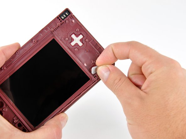
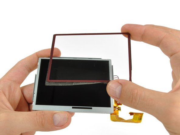
Firmly grasp the upper screen, and lifting from the right edge, pull the upper screen off of the upper LCD.
-


Cancelar: No complete esta guía.
16 personas más completaron esta guía.


6 comentarios
I think a soldering tool needs to be added to the tool list. It may be a given for pros, but for amateur fixit wannabes this could be useful information to have before step 44.
Why is there two Upper LCD Replacements here? makes no sense, Can i have a explanation for this? One is "Difficult", and another is "Very difficult"
there's two different options?? why does this got to be so complicated. is there any place that does replacements for me?
You wait til the final STEP 44 to mention soldering is required…!?!
PLEASE add soldering into required tools… I just spent an hour disassembling the %#*@ thing to be told I need to buy a soldering kit.