Esta versión puede contener ediciones incorrectas. Cambiar a la última instantánea verificada.
Qué necesitas
-
-
Retira los dos tornillos Phillips que fijan la tapa de la batería a la parte posterior de la consola portátil.
-
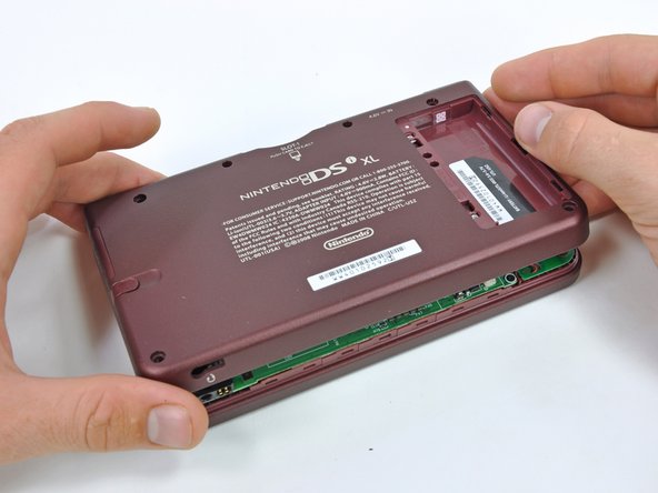
Quita la tapa de la batería de la parte posterior de la DSi XL.
-
-
Este paso está sin traducir. Ayuda a traducirlo
-
Remove the four rubber screw covers on the lower case by prying them up with a push pin.
-
-
Este paso está sin traducir. Ayuda a traducirlo
-
Remove the following seven Phillips screws that secure the lower case to the rest of the DSi XL:
-
Four silver 5.3 mm screws
-
Two black 5.3 mm screws
-
One black 2.5 mm screw
-
-
Este paso está sin traducir. Ayuda a traducirlo
-
Insert a spudger between the upper and lower case at the bottom left corner of the DSi.
-
Slide the spudger along the bottom edge of the upper case to release the latches securing the upper case to the lower case.
-
-
Este paso está sin traducir. Ayuda a traducirlo
-
Lift the lower case from the front edge.
-
Rotate the lower case away from the DSi.
-
-
Este paso está sin traducir. Ayuda a traducirlo
-
Using a spudger, pry the SD card/right shoulder button connector off its socket.
-
Pry the volume button/left shoulder button connector off its socket on the motherboard with a spudger.
-
-
-
Este paso está sin traducir. Ayuda a traducirlo
-
Lift the Wi-Fi board up off its socket on the motherboard.
-
-
Este paso está sin traducir. Ayuda a traducirlo
-
Use a spudger to pry the microphone cable off the motherboard.
-
-
Este paso está sin traducir. Ayuda a traducirlo
-
Using the flat end of a spudger, flip up the retaining flap on the camera ribbon ZIF connector.
-
Use the pointed end of a spudger to pull the camera ribbon from the ZIF connector.
-
-
Este paso está sin traducir. Ayuda a traducirlo
-
Using the flat end of a spudger, flip up the retaining flap on the touchscreen cable ZIF connector.
-
With the pointed end of the spudger, pull the touchscreen cable from its connector on the motherboard.
-
-
Este paso está sin traducir. Ayuda a traducirlo
-
Using the flat end of a spudger, flip up the retaining flap on the backlight cable ZIF connector.
-
With the pointed end of the spudger, pull the backlight cable from its connector on the motherboard.
-
-
Este paso está sin traducir. Ayuda a traducirlo
-
Using the flat end of a spudger, flip up the retaining flap on the lower display data cable ZIF connector.
-
With the pointed end of the spudger, pull the lower display data cable from its connector on the motherboard.
-
-
Este paso está sin traducir. Ayuda a traducirlo
-
Using the flat end of a spudger, flip up the retaining flap on the ZIF connector for the D-Pad/power button cable.
-
With the pointed end of the spudger, pull the D-Pad/power button cable from its connector on the motherboard.
-
-
Este paso está sin traducir. Ayuda a traducirlo
-
Using the flat end of the spudger, pry the battery cable up off its socket on the motherboard.
-
-
Este paso está sin traducir. Ayuda a traducirlo
-
Remove the screws securing the motherboard to the upper case:
-
A single 2.5 mm silver Phillips screw
-
Four 3.7 mm black Phillips screws
-
-
Este paso está sin traducir. Ayuda a traducirlo
-
Deroute the microphone and antenna cables through the slot in the motherboard.
-
-
Este paso está sin traducir. Ayuda a traducirlo
-
Using the flat end of a spudger, flip up the retaining flap on the upper display data cable ZIF connector.
-
With the pointed end of the spudger, pull the upper display data cable from its connector on the underside of the motherboard.
-


Cancelar: No complete esta guía.
20 personas más completaron esta guía.

