Esta versión puede contener ediciones incorrectas. Cambiar a la última instantánea verificada.
Qué necesitas
-
-
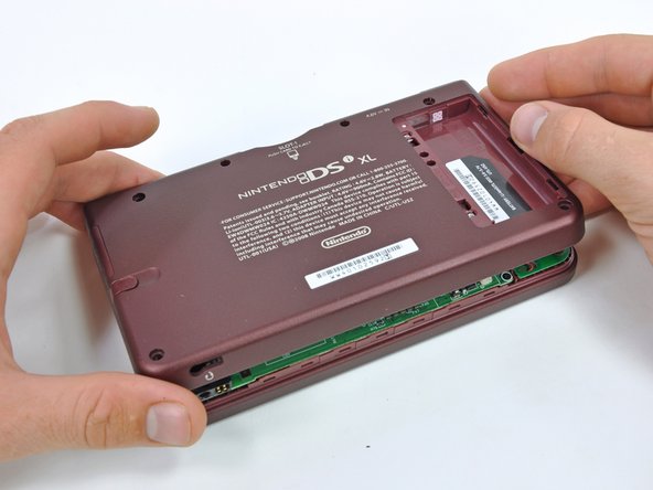
Retira los dos tornillos Phillips que fijan la tapa de la batería a la parte posterior de la consola portátil.
-
Quita la tapa de la batería de la parte posterior de la DSi XL.
-
-
Este paso está sin traducir. Ayuda a traducirlo
-
Remove the four rubber screw covers on the lower case by prying them up with a push pin.
-
-
Este paso está sin traducir. Ayuda a traducirlo
-
Remove the following seven Phillips screws that secure the lower case to the rest of the DSi XL:
-
Four silver 5.3 mm screws
-
Two black 5.3 mm screws
-
One black 2.5 mm screw
-
-
Este paso está sin traducir. Ayuda a traducirlo
-
Insert a spudger between the upper and lower case at the bottom left corner of the DSi.
-
Slide the spudger along the bottom edge of the upper case to release the latches securing the upper case to the lower case.
-
-
Este paso está sin traducir. Ayuda a traducirlo
-
Lift the lower case from the front edge.
-
Rotate the lower case away from the DSi.
-
-
Este paso está sin traducir. Ayuda a traducirlo
-
Using a spudger, pry the SD card/right shoulder button connector off its socket.
-
Pry the volume button/left shoulder button connector off its socket on the motherboard with a spudger.
-
-
Este paso está sin traducir. Ayuda a traducirlo
-
Lift the Wi-Fi board up off its socket on the motherboard.
-
-
-
Este paso está sin traducir. Ayuda a traducirlo
-
Use a spudger to pry the microphone cable off the motherboard.
Note that the WiFi board has already been removed here! Including this extra step would be convenient here '-)
-
-
Este paso está sin traducir. Ayuda a traducirlo
-
Using the flat end of a spudger, flip up the retaining flap on the camera ribbon ZIF connector.
-
Use the pointed end of a spudger to pull the camera ribbon from the ZIF connector.
-
-
Este paso está sin traducir. Ayuda a traducirlo
-
Using the flat end of a spudger, flip up the retaining flap on the touchscreen cable ZIF connector.
-
With the pointed end of the spudger, pull the touchscreen cable from its connector on the motherboard.
-
-
Este paso está sin traducir. Ayuda a traducirlo
-
Using the flat end of a spudger, flip up the retaining flap on the backlight cable ZIF connector.
-
With the pointed end of the spudger, pull the backlight cable from its connector on the motherboard.
-
-
Este paso está sin traducir. Ayuda a traducirlo
-
Using the flat end of a spudger, flip up the retaining flap on the lower display data cable ZIF connector.
-
With the pointed end of the spudger, pull the lower display data cable from its connector on the motherboard.
-This is where you can replace the charger port. i may change this comment later from May 21-June 5
-
-
Este paso está sin traducir. Ayuda a traducirlo
-
Using the flat end of a spudger, flip up the retaining flap on the ZIF connector for the D-Pad/power button cable.
-
With the pointed end of the spudger, pull the D-Pad/power button cable from its connector on the motherboard.
-
-
Este paso está sin traducir. Ayuda a traducirlo
-
Using the flat end of the spudger, pry the battery cable up off its socket on the motherboard.
The battery connectors (socket) on the mother board are extremely fragile, so care should be taken to avoid breaking them.
Other than this, the instructions given are precise and straighforward. I do agree with the other comments about step 20.
-
-
Este paso está sin traducir. Ayuda a traducirlo
-
Remove the screws securing the motherboard to the upper case:
-
A single 2.5 mm silver Phillips screw
-
Four 3.7 mm black Phillips screws
the battery connector was (for me) extremely hard to remove. I broke the socket completely off the board hand had to hard solder it directly back.
-
-
Este paso está sin traducir. Ayuda a traducirlo
-
Deroute the microphone and antenna cables through the slot in the motherboard.
-
-
Este paso está sin traducir. Ayuda a traducirlo
-
Using the flat end of a spudger, flip up the retaining flap on the upper display data cable ZIF connector.
-
With the pointed end of the spudger, pull the upper display data cable from its connector on the underside of the motherboard.
This step is unnecessary. The ribbon is a total pain in the butt to get back in, and if you dont get it PERFECT, the DS will not even fire back up. Unless it is absolutely necessary to remove it... DON'T !!! ( Personal experience, Everything else was SPOT ON) THANK YOU FOR THE HELP, saved me a lot of $$$
Fantastic! Fixed my daughter's irreplaceable DSi XL - you should see her smiles!! Not sure about step 20 I did this before reading the comments (guess there's a message there). Thanks so much whoever wrote this - you're a legend and you've made a child very happy (and a dad too thereby).
I put mine back together for my daughter with the new bottom screen, but it won't power on. It tries but won't I'm assuming that this ribbon is the cause.
The instructions are perfect though! Great thing to have these instructions it's a tremendous help! :-)
YHWH is the god of all knowledge. Put a piece of transparent tape on the ribbon cable to give more leverage to pull the cable up to slide it into the slot. Also turn the motherboard slightly so that you can get it closer to the cable.
I didn't get mine completely reinserted at first. The symptom I experienced when powering it back on is the power light comes on briefly and the bottom screen light flashes, then they both shut off. No flash from the upper display. Had to try reinserting 3 times before I had it in completely. I agree, DON'T REMOVE if you don't have to.
-
-
Este paso está sin traducir. Ayuda a traducirlo
-
With the console still upside-down, open the DSi XL slightly.
-
Push the lower display away from the upper case.
-
Remove the lower display from the DSi XL.
-
-
Este paso está sin traducir. Ayuda a traducirlo
-
Insert a spudger between the touchscreen and top right corner of the display.
-
Slide the spudger down the right side of the display to free the edge of the touchscreen.
When removing the digitizer, note, there is an adhesive around the perimeter of the mating surface of digitizer-to-lcd screen (keeps dust out also). If your new screen or digitizer does not have one (mine didn't) try to be gentle when removing the digitizer to avoid damaging the adhesive. Work above or below the adhesive strip- whatever helps keep it intact with the component you aren't replacing but if it is too stuck on one side or another you can always peel it off the other component after the fact. DON'T STRETCH IT or it won't lay nicely.
-
-
Este paso está sin traducir. Ayuda a traducirlo
-
Continue around the bottom right corner of the display with the spudger.
-
Slide the spudger along the bottom edge of the touchscreen to separate it from the display.
-
-
Este paso está sin traducir. Ayuda a traducirlo
-
Continue around the bottom left corner of the display with a spudger.
-
Slide the spudger along the left edge of the touchscreen to remove it from the display.
-
-
Este paso está sin traducir. Ayuda a traducirlo
-
With three sides freed, remove the touchscreen from the lower display.
The plastic frame has to be removed from the old touchscreen, too. It's an adhesive. My new touchscreen didn't have one. When reattaching, insert the frame back into the DSi case first, then carefully drop the new touchscreen down on top of it to try to get it to line up correctly.
Also, after everything was done, I had to run the touchscreen calibration in the DSi menu to get the touchscreen to work properly.
During re-install, when reattaching the digitizer it has to be on fairly precise otherwise the digitizer-LCD screen assembly will not fit into the "pocket" easily (won't sit all the way flush) therefore it is advisable to loosely attach the two pieces with the adhesive barely touching (to allow the pieces to slide slightly into the correct spot) or to instead install the digitizer by itself into the "pocket" then the LCD screen after (with the adhesive strip already attached to the LCD screen beforehand. Either way be careful not to get anything caught in this gap (hair, lint, fingerprints, etc) otherwise it may be annoyingly visible.
-


Cancelar: No complete esta guía.
15 personas más completaron esta guía.

3 comentarios
DSI XL Lower LCD ZIF Socket replacement - Please help!!
Hi All, I have a DSi XL which i am trying to rescue from someone who has done a bad job of attempting a repair! It has been taken apart, although the guy didn't know how ZIF sockets work and has broken two of them. The 37 pin Lower LCD ZIF socket, and the 15 pin power board ZIF socket. I am experienced electronic engineer and and hand soldered SMD components before so i think i can replace these and get this DSi working again. My only problem is, i cannot find any reference to exactly what these sockets are or where to buy some! Can anyone offer any information about these sockets at all? I really want to get hold of some and get this back in action. Any help locatin the correct parts would be very very welcomed.
Many thanks in advance all
Matt Stroud
Great set of instructions - Thanks
Replaced the lower screen for the first time with no problems
Thanks
Hello and thanks for sharing.
I have two units of this model.
The first one sunk in water and I’m not sure it can be fixed (can it?)
The other one’s lower screen got a slight crack when it was hit by the kids using it with the device pen, and the touch response has been limited since. I was wondering if I can take out only the touch layer of the sunken device’s screen and install it on the new one.
Thanks.
rust/white powder built up on a screw and can’t unscrew it
Eco - Contestar