Esta versión puede contener ediciones incorrectas. Cambie a la última instantánea verificada.
Qué necesitas
-
-
Retira los dos tornillos Phillips que fijan la tapa de la batería a la parte posterior de la consola portátil.
-
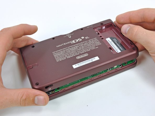
Quita la tapa de la batería de la parte posterior de la DSi XL.
-
-
Este paso está sin traducir. Ayuda a traducirlo
-
Remove the four rubber screw covers on the lower case by prying them up with a push pin.
-
-
Este paso está sin traducir. Ayuda a traducirlo
-
Remove the following seven Phillips screws that secure the lower case to the rest of the DSi XL:
-
Four silver 5.3 mm screws
-
Two black 5.3 mm screws
-
One black 2.5 mm screw
-
-
-
Este paso está sin traducir. Ayuda a traducirlo
-
Insert a spudger between the upper and lower case at the bottom left corner of the DSi.
-
Slide the spudger along the bottom edge of the upper case to release the latches securing the upper case to the lower case.
-
-
Este paso está sin traducir. Ayuda a traducirlo
-
Lift the lower case from the front edge.
-
Rotate the lower case away from the DSi.
-
-
Este paso está sin traducir. Ayuda a traducirlo
-
Using a spudger, pry the SD card/right shoulder button connector off its socket.
-
Pry the volume button/left shoulder button connector off its socket on the motherboard with a spudger.
-
-
Este paso está sin traducir. Ayuda a traducirlo
-
Using the flat end of a spudger, flip up the retaining flap on the ZIF connector for the D-pad/power button cable.
-
With the pointed end of the spudger, pull the D-pad/power button cable from its connector on the motherboard.
-
-
Este paso está sin traducir. Ayuda a traducirlo
-
Using the flat end of the spudger, carefully pry the battery cable out of its socket on the motherboard.
-
-
Este paso está sin traducir. Ayuda a traducirlo
-
Remove the seven 2.5 mm silver screws securing the power board to the upper case.
-
Lift the power board off the upper case.
-
-
Este paso está sin traducir. Ayuda a traducirlo
-
Open the display slightly, and push the D-pad up through the upper case.
-
Lift the D-Pad from the handheld device.
-


Cancelar: No complete esta guía.
8 personas más completaron esta guía.


Un comentario
Be very careful removing the screws - a Google search returns page after page of people who stripped their screws trying to remove the lower case or the power board. My lower case may be permanently attached now. If I did it over again, I would consider dripping a tiny amount of WD40 onto the screws and letting it seep in for a day before I tried removing them...