Esta guía ha sufrido modificaciones. Revisa la última versión sin revisar.
Introducción
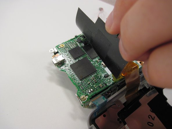
Replacing the logic board of a Nikon Coolpix 3500
Qué necesitas
-
-
Unlatch the battery cover and slide the cover out. Place cover to the side, it will not be needed for the next few steps.
-
Remove the battery.
-
Remove the battery cover without using excessive force. Keep in mind this cover is fragile.
-
-
-
Remove the two 4.5 mm screws that sit next to the battery slot.
-
Remove the 3 mm screw that sits below the CF card slot.
-
Remove the 4.5 mm screw that sits above the digital I/O cover.
-
-
-
-
Detach the grey-capped wire.
-
Detach the green chip that sits next to the blue wires.
-


To reassemble your device, follow these instructions in reverse order.
To reassemble your device, follow these instructions in reverse order.
Equipo

Cal Poly, Team 30-38, Garner Spring 2010 Miembro de Cal Poly, Team 30-38, Garner Spring 2010
CPSU-GARNER-S10S30G38
5 Miembros
11 Guías creadas