Esta versión puede contener ediciones incorrectas. Cambie a la última instantánea verificada.
Qué necesitas
-
Este paso está sin traducir. Ayuda a traducirlo
-
Unlatch the battery cover and slide the cover out. Place cover to the side, it will not be needed for the next few steps.
-
Remove the battery.
-
Remove the battery cover without using excessive force. Keep in mind this cover is fragile.
-
-
Este paso está sin traducir. Ayuda a traducirlo
-
Remove the two 4.5 mm screws that sit next to the battery slot.
-
Remove the 3 mm screw that sits below the CF card slot.
-
Remove the 4.5 mm screw that sits above the digital I/O cover.
-
-
Este paso está sin traducir. Ayuda a traducirlo
-
Remove the two 4.5 mm screws that sit inside the battery slot.
-
-
Este paso está sin traducir. Ayuda a traducirlo
-
Remove the two 5 mm screws that sit near the camera strap eyelet.
-
Remove the camera strap eyelet.
-
-
-
Este paso está sin traducir. Ayuda a traducirlo
-
Remove the 5 mm screw and cap that were underneath the camera strap eyelet.
-
-
Este paso está sin traducir. Ayuda a traducirlo
-
Remove the five 3.5 mm screws that sit at the bottom of the camera.
-
Remove the grey plastic piece, which the five screws held in place, by gently detaching the front cover.
-
-
Este paso está sin traducir. Ayuda a traducirlo
-
Using a spudger, detach the white-capped wire.
-
Using a spudger, detach the orange-capped wire and set the front cover aside.
-
-
Este paso está sin traducir. Ayuda a traducirlo
-
Disconnect the grey-capped wire from the motherboard.
-
Disconnect the blue wire attached to the green chip from the center of the motherboard.
-
-
Este paso está sin traducir. Ayuda a traducirlo
-
Remove the 3.5 mm screw from the motherboard next to the rotating lens.
-
Invert the motherboard and lens toward the orange and blue wires still connecting the motherboard to the LED screen.
-
-
Este paso está sin traducir. Ayuda a traducirlo
-
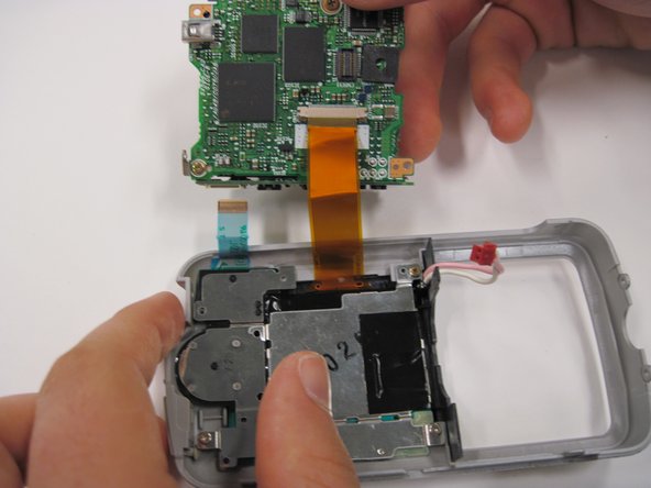
Disconnect the blue wire connecting the motherboard to the LED screen.
-
Disconnect the orange wire using a spudger while pushing out horizontally.
-
Disconnect the red capped wire from the motherboard.
-
Lift the motherboard and lens (still connected) out of the back case.
-
-
Este paso está sin traducir. Ayuda a traducirlo
-
Lift up on the black covering and remove the orange wire connecting the lens to the motherboard.
-


