Esta versión puede contener ediciones incorrectas. Cambie a la última instantánea verificada.
Qué necesitas
-
Este paso está sin traducir. Ayuda a traducirlo
-
Gently insert a plastic opening tool near the top of the Nexus 7 between the rear panel and the front panel assembly.
-
Carefully run the plastic opening tool along the top edge to pry the rear panel away from the front panel assembly of the Nexus 7.
-
-
Este paso está sin traducir. Ayuda a traducirlo
-
Insert the plastic opening tool between the rear panel and the front panel assembly near the power button and pry up at several points along the right edge of the Nexus 7.
-
-
Este paso está sin traducir. Ayuda a traducirlo
-
Pry up the rear panel along the left edge using the method described in previous steps.
-
-
Este paso está sin traducir. Ayuda a traducirlo
-
Gently lift and remove the rear panel up off the front panel assembly.
-
-
-
Este paso está sin traducir. Ayuda a traducirlo
-
Using the tip of a spudger, push first on one side then the other to "walk" the battery cable straight out of its socket on the motherboard.
-
-
Este paso está sin traducir. Ayuda a traducirlo
-
Peel back the copper ESD shielding covering the bottom of the motherboard.
-
If you're just replacing the micro usb charge port, there is no need to peel back the copper heatsink like in the photo, the speaker assembly can simply be moved out of the way once unscrewed. If the speakers are to be replaced simply peel back the bottom corner to expose the speaker connection. Leave the rest of the heatsink shield alone.
-
-
Este paso está sin traducir. Ayuda a traducirlo
-
Using the tip of a spudger, push the speaker cable straight out of its socket on the motherboard.
-
-
Este paso está sin traducir. Ayuda a traducirlo
-
Remove the following screws securing the speaker assembly to the display assembly:
-
Two 4.25 mm black Phillips screws
-
One 3.2 mm silver Phillips screw
-
-
Este paso está sin traducir. Ayuda a traducirlo
-
Lift and remove the speaker assembly out of the Nexus 7.
-
-
Este paso está sin traducir. Ayuda a traducirlo
-
Use the tip of a spudger to peel back the cloth tape covering the headphone jack and the I/O assembly cable.
-
-
Este paso está sin traducir. Ayuda a traducirlo
-
Use the tip of a spudger to flip up the retaining flap on the I/O assembly data ribbon cable ZIF socket.
-
-
Este paso está sin traducir. Ayuda a traducirlo
-
Remove the following screws securing the I/O assembly cable to the Nexus 7:
-
Three 3.2 mm silver Phillips screws
-
Two 2.3 mm black Phillips screws
-
-
Este paso está sin traducir. Ayuda a traducirlo
-
Without stressing the cable, and minding any tape that may still be holding the cable in place, gently lift the headphone jack up off its placement pins.
-
-
Este paso está sin traducir. Ayuda a traducirlo
-
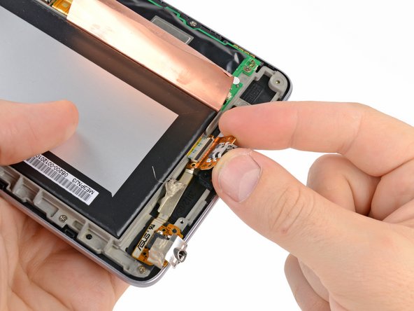
In a similar fashion, lift the micro-USB port up off its retaining pins.
-
Lift and remove the I/O assembly cable out of the Nexus 7.
-


Cancelar: No complete esta guía.
146 personas más completaron esta guía.

32 comentarios
This fix isn't too much of a pain if you can find the parts! The tape on the lower-left hand side was, oddly, a bit of a pain for me. Make sure you try to remove it from the left, and not from the right!
Got the cable and some recommended tools on Ebay for $30. Just did this on my old N7 and it works perfect now. Head up tho, the recommended tools didn't come with a small enough head for the two 2.3 mm black Phillips screws. Luckily i did have a super small one. Don't strip those or you SOL. Also the cable doesn't come with the headphone jack cover. it is held on with just tape so take that from the original cable.
Cable: http://www.ebay.com/itm/IO-PORT-CHARGER-...
Do a ebay search for "Nexus 7 I/O". Should pop up. Look for cheaper ones than the $60 ones.
Thank you so much for the clear guide. My Nexus 7 2012 is charging again! I ordered the part here: http://www.asusparts.eu/Asus-08301-00522...