Esta versión puede contener ediciones incorrectas. Cambiar a la última instantánea verificada.
Qué necesitas
-
Este paso está sin traducir. Ayuda a traducirlo
-
Insert a SIM card eject tool, bit, or a straightened paperclip into the small hole in the SIM card tray, located at the top left edge of the phone.
-
Press to eject the tray.
-
Remove the tray from the phone.
-
-
Este paso está sin traducir. Ayuda a traducirlo
-
Heat an iOpener and apply it to the left edge of the phone for two minutes.
-
As you wait, take note of the the following areas:
-
Display cable—be careful not to slice too deeply near the edge here, or you may damage the display cable.
-
Fingerprint sensor cable—be careful not to slice too deeply near the edge here, or you may damage the fingerprint sensor cable.
-
-
Este paso está sin traducir. Ayuda a traducirlo
-
Apply a suction cup to the screen, as close to the heated edge as possible.
-
Pull on the suction cup with strong, steady force to create a gap in the seam.
-
Insert the point of an opening pick into the gap.
-
-
Este paso está sin traducir. Ayuda a traducirlo
-
Slide the opening pick along the edge to slice through the adhesive.
-
Leave an opening pick in the seam to prevent the adhesive from re-sealing.
-
-
Este paso está sin traducir. Ayuda a traducirlo
-
Heat the top edge of the phone with an iOpener.
-
Carefully slice around the corner and through the top edge to separate the adhesive.
-
-
Este paso está sin traducir. Ayuda a traducirlo
-
Heat the screen's right edge with an iOpener.
-
Be careful not to slice too deeply near the cables to avoid damaging them.
-
Use an opening pick to slice along the right edge to separate the adhesive.
-
-
Este paso está sin traducir. Ayuda a traducirlo
-
Repeat the previous steps to heat and slice the bottom edge of the phone.
-
-
Este paso está sin traducir. Ayuda a traducirlo
-
Carefully lift up the left edge of the screen and cut away remaining adhesives with an opening pick.
-
-
Este paso está sin traducir. Ayuda a traducirlo
-
Swing open the screen and prop it up with a small box as you work on disconnecting the flex cables.
-
-
-
Este paso está sin traducir. Ayuda a traducirlo
-
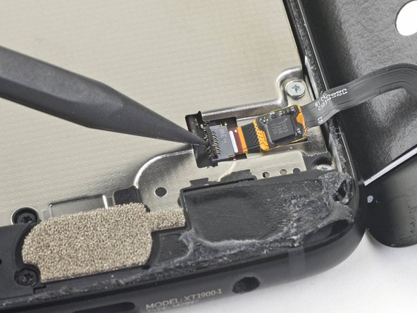
Slide the point of a spudger underneath the fingerprint sensor cable and gently pry up to loosen the cable from the phone.
-
-
Este paso está sin traducir. Ayuda a traducirlo
-
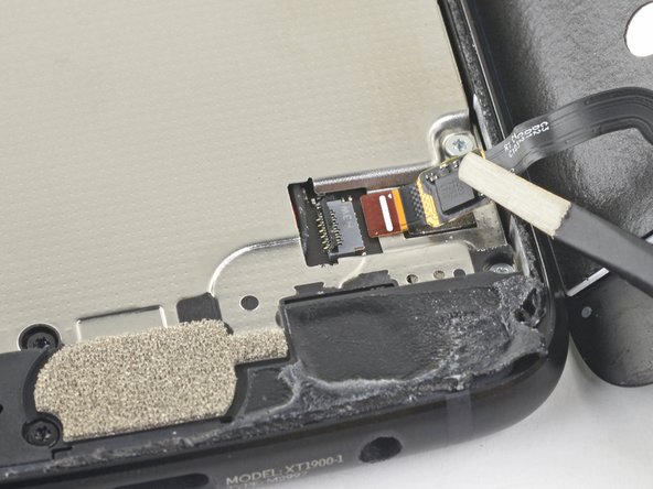
Use the point of a spudger to flip up the lock bar on the fingerprint sensor's ZIF socket, near the bottom right of the phone.
-
Use tweezers to carefully slide the fingerprint sensor cable out of the socket.
-
-
Este paso está sin traducir. Ayuda a traducirlo
-
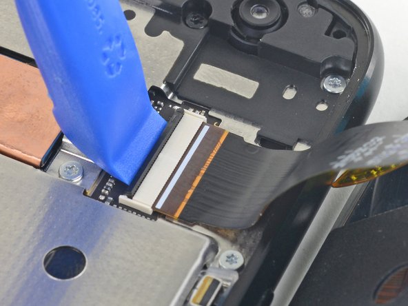
Use an opening tool to flip up the wide lock bar on the display cable's ZIF socket, near the top right of the phone.
-
Use tweezers to carefully slide the display cable out of the ZIF socket.
-
-
Este paso está sin traducir. Ayuda a traducirlo
-
Remove the following twenty screws securing the midframe:
-
Eleven silver 2.7 mm-long T3 screws
-
Nine black 3.6 mm-long T4 screws
-
The midframe is still held in place by clips.
-
-
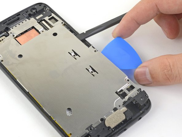
Este paso está sin traducir. Ayuda a traducirlo
-
Insert the flat end of a spudger under the right edge of the metal midframe and pry up to loosen the midframe.
-
Insert an opening pick in the edge to hold the midframe in place.
-
-
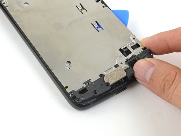
Este paso está sin traducir. Ayuda a traducirlo
-
Insert the flat end of a spudger under the lower right edge of the midframe and pry up to release the midframe clip.
-
-
Este paso está sin traducir. Ayuda a traducirlo
-
Grasp the lower edge of the midframe and pull the edge slightly to the right, to clear the metal midframe clip.
-
-
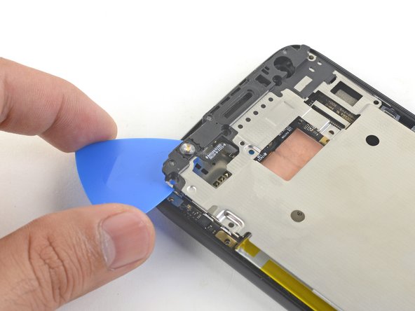
Este paso está sin traducir. Ayuda a traducirlo
-
Insert the point of an opening pick under the top left corner of the midframe and twist slightly to release the top clip.
-
-
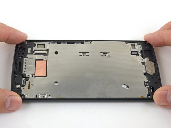
Este paso está sin traducir. Ayuda a traducirlo
-
Remove the midframe.
-
Align the the midframe's top edge to the phone and press it into position.
-
Shift the bottom edge slightly to the left, to maneuver the left metal midframe clip underneath the phone edge.
-
Press the midframe's bottom edge into position.
-
-
Este paso está sin traducir. Ayuda a traducirlo
-
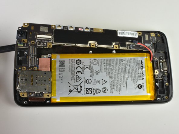
Insert the point of a spudger underneath the top edge of the battery connector.
-
Gently pry up the connector to disconnect the battery.
-
-
Este paso está sin traducir. Ayuda a traducirlo
-
Remove the T3 screw that is holding in the motherboard.
-
-
Este paso está sin traducir. Ayuda a traducirlo
-
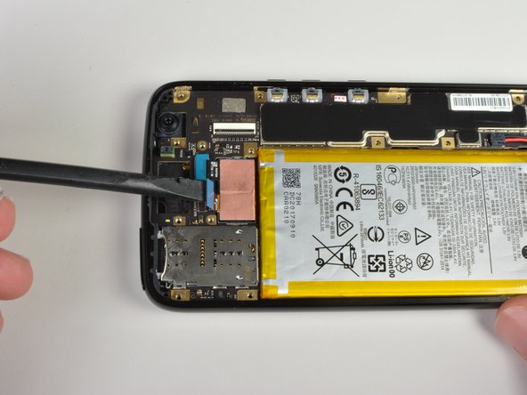
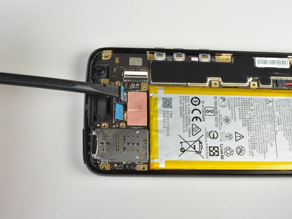
Use flat edge of the spudger to pry up the two blue connectors near the top of the device.
-
-
Este paso está sin traducir. Ayuda a traducirlo
-
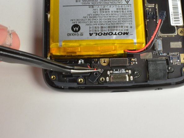
Use flat side of spudger to pry up connector near the bottom of the device.
-
-
Este paso está sin traducir. Ayuda a traducirlo
-
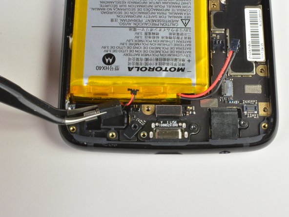
Using a pair of tweezers disconnect the vibrating motors connector near the bottom of the device.
-


Cancelar: No complete esta guía.
7 personas más completaron esta guía.
Equipo

Cal Poly, Team S18-G4, Livingston Winter 2018 Miembro de Cal Poly, Team S18-G4, Livingston Winter 2018
CPSU-LIVINGSTON-W18S18G4
4 Miembros
13 Guías creadas
8 comentarios
I have Moto x4 mother board
Can you call me 833100taa1
I am from Hyderabad i need moto X4 mother board
Anana malladi r y working at