Introducción
This guide will teach you how to safely remove the headphone jack from your Surface Pro 3. The guide starts by removing the screen and digitizer and then goes right into removing the headphone jack.
Qué necesitas
-
-
To remove the display, first soften the adhesive by applying heat. You can use a heat pad, heat gun, or iOpener. In a pinch, a hair dryer can also work.
-
Steadily and evenly heat the perimeter of the display until it's too hot to touch, and try to maintain that temperature for several minutes.
-
-
-
Use a suction cup or an iSclack to pull up on the glass and create a slight gap between the glass and the metal frame.
-
Carefully insert an opening pick into the gap between the screen and the device to cut the adhesive.
-
Slide the pick around the sides and bottom of the display to cut the adhesive. Apply more heat as needed.
Be very very careful!! Don’t cut yourself. Wear gloves.
-
-
-
Continue to heat sections of the screen with the heat gun.
-
As you make your way around the screen with the heat gun, use the plastic opening tool and the opening picks to pry the screen loose.
I used an inexpensive variable heat gun with a dial. It was perfect. My fixed temperature gun would have ruined it. There are two small vents on either side of the screen near the top. Start there and work down on each side. I didn’t have opening picks to keep the glass separated from the body. So, I used blank Cards Against Humanity I found lying around.
I watched two popular videos. Neither helped and were no better than these instructions. In one video, the guy heats and smashes his way around the display with metal tool. Mistake! Don’t do this even if the screen is broken. This causes glass shards to go everywhere and will force you to replace the adhesive before installing a new screen. You can’t reuse adhesive if it is full of glass. Another video uses a heat gun one side at a time and simply sliding a pick along the edge working around the Surface. This didn’t work. The person had already removed the screen once before and started the second removal before the video.
CAUTION: if you insert the picks too far, you risk damaging the display (separating the glass from the display circuitry).
The display circuitry is 14 mm from the side edges, 10 mm from the top edge, and 6 mm from the bottom edge.
thanks a lot for your comment
-
-
-
Lift the screen up carefully so that no wires are torn.
This guide misses a CRUCIAL NOTE on this step.
On this step, from Picture 1 to Picture 2 the device is rotated so the Windows logo on the glass is actually on the left hand side.
You *must* rotate the device otherwise you will risk damaging the cables, as it folds open like a book.
Pain in the ass! One has to wonder why they couldn’t use magnetic connections instead of this goo, black thing that even to replace is so %#*@ annoying to say the least! After trying to remove a broken screen I didn’t even use the adhesive strips. I used the ones I had there and to be frank it’s better since:
a) I couldn’t get the new screen properly aligned and to fit to perfection even though the touch works flawlessly (w/ some adhesive tape on the top to hide the gaps) and
b) who knows? you may as well need to reopen it again. Hopefully not.Hopefully it will be easier. Hopefully never again!!!
P.S.:
-
-
-
-
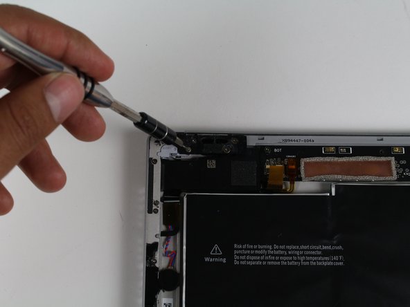
Remove the single 4 mm T3 Torx screw securing the display cable.
-
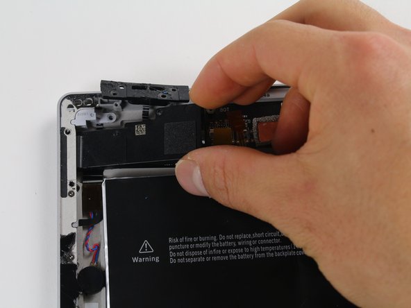
Lift the connector to disconnect the cable.
It's always best to disconnect the battery before disconnecting the display cable. Ensuring there is no power to the device will also ensure you don't damage the backlight components when disconnecting the display. You should also make sure to reattach the display cable before reattaching the battery cable when putting it back together.
There is also a tiny little board between the ribbon cable and motherboard. Be sure not to lose it!!! If you do the part is 1631 LCD Contact Shield Plate.
You’ll notice a spring on the back of your old screen. The new screens don’t have that spring so it will need to be transferred over by the heat gun trick.
The instructions do not mention the bridge connectors under the connectors - tiny little rectangle boards with gold connector dots. There is one under the battery connector and under the display connector. It is sandwiched in between the board and the connector. You may not even notice the bridge connectors. In fact the pictures here with the cable connectors off are showing the bridge connectors under the cable connectors still lying on the motherboard. Go ahead and remove the bridge connectors with tweezers. These connectors are just lying on the motherboard and WILL FALL OFF getting lost without noticing it. The cable connectors do not work without the bridge connectors installed. Good news is the connectors are keyed and fit only one way.
BTW: Both screws on the battery and display connector were T3’s and the same size.
Hi!. What’s the name of the band connector and what’s the name of the connector in both sides?
-
-
-
Remove the single 4 mm T5 Torx screw.
-
Remove the four 4 mm T3 Torx screws.
-
Remove the single 7 mm T3 Torx screw.
-


To reassemble your device, follow these instructions in reverse order.
To reassemble your device, follow these instructions in reverse order.
Cancelar: No complete esta guía.
4 personas más completaron esta guía.
Equipo

Cal Poly, Team 12-18, Maness Fall 2015 Miembro de Cal Poly, Team 12-18, Maness Fall 2015
CPSU-MANESS-F15S12G18
5 Miembros
31 Guías creadas
I just replaced both my screen and battery. It took four hours and a couple of wrong turns but I was successful learning what to do next time. However, I am not sure I would do it again.
It takes more heat than one imagines - all most too much and made me queasy fearing I was going to damage something. I would say it actually too hot and likely to damage something so be careful and do not prolong the removal. To get started I used a glass top warming/buffet heating tray set to about 200 degrees. I turned the surface pro glass side down before turning it one so it would heat gradually with the tray. I let it heat for 15 minutes. In end, I am not sure it helped or not by starting this way. This was not an easy removal so I shudder to think how worse it would have been if this didn’t help. I used a variable heat gun for the remaining steps. My screen was broken so breaking it further while nerve racking was not going to be catastrophic.
michael jones - Contestar
I attempted battery replacement, but during disassembly, i damaged the display by inserting the picks to far, and separating the display circuitry from the glass.
I used a Milwaukee precision hot tool model 1400, which has only a fixed heat setting, but it worked perfectly to soften the adhesive.
(I was very careful to heat the entire glass panel by playing the heat gun over the entire surface so that it would expand uniformly.
Robert Gerlach - Contestar
I just broke mine during the heating process as well…. The glue at the corner was so strong that I cant even slip a blade into the edge… Then when keep applying heat using a hair dryer at low tempreture the glass expanded too much and broke……
C Y Wong - Contestar
If you have never done this repair, YOU WILL SHATTER THE SCREEN! I've repaired dozens of these over the last several years for my client's and I still shatter them. It's a 98% probability that you will break the glass; it's very thin and shatters easily. Be prepared.
Gregg Stanley - Contestar