Esta versión puede contener ediciones incorrectas. Cambie a la última instantánea verificada.
Qué necesitas
-
-
Con la carcasa cerrada, coloca el Unibody con la parte superior hacia abajo sobre una superficie plana.
-
Presiona el lado ranurado de la pestaña de apertura de la puerta de acceso, lo suficiente como para poder agarrar el extremo libre. Levanta la pestaña de apertura hasta que quede vertical.
-
-
-
Retira los siguientes ocho tornillos que aseguran la carcasa inferior al chasis:
-
Un tornillo Phillips de 3 mm.
-
Tres tornillos Phillips de 13.5 mm.
-
Cuatro tornillos Phillips de 3.5 mm.
-
-
Este paso está sin traducir. Ayuda a traducirlo
-
Remove the four 10.3 mm Phillips screws securing the mid wall to the upper case.
-
-
Este paso está sin traducir. Ayuda a traducirlo
-
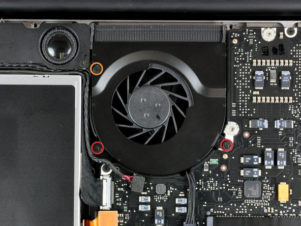
Use a spudger to pry the fan connector straight up off the logic board.
-
-
Este paso está sin traducir. Ayuda a traducirlo
-
Remove the following three screws securing the fan to the upper case:
-
Two 5 mm Phillips screws.
-
One 7 mm Phillips screw.
-
-
-
Este paso está sin traducir. Ayuda a traducirlo
-
Each connector is different, so the following steps will show you how disconnect each in detail.
-
-
Este paso está sin traducir. Ayuda a traducirlo
-
Remove the single Phillips screw securing the battery cable cover to the upper case.
-
Remove the battery cable cover from the upper case.
-
-
Este paso está sin traducir. Ayuda a traducirlo
-
Use a spudger to pry the battery level indicator cable connector straight up off the logic board.
-
-
Este paso está sin traducir. Ayuda a traducirlo
-
Disconnect the battery cable connector by pulling it straight away from the logic board.
-
-
Este paso está sin traducir. Ayuda a traducirlo
-
Using the tip of a spudger, flip up the keyboard ribbon cable retaining flap.
-
Pull the keyboard ribbon cable straight out of its socket.
-
If the smaller connector at the right side of the keyboard ribbon cable is populated by another small black ribbon cable, remove it in a similar way to the above.
-
-
Este paso está sin traducir. Ayuda a traducirlo
-
Use the flat end of a spudger to pry the trackpad connector straight up off the logic board.
-
-
Este paso está sin traducir. Ayuda a traducirlo
-
Use the tip of a spudger to flip up the locking lever to release the IR sensor ribbon cable from its socket.
-
Use the tip of a spudger to pull the IR sensor ribbon cable straight away from the logic board.
-
-
Este paso está sin traducir. Ayuda a traducirlo
-
Use the flat end of a spudger to pry the hard drive cable connector straight up off the logic board.
-
-
Este paso está sin traducir. Ayuda a traducirlo
-
Use the flat end of a spudger to pry the optical drive cable connector straight up off the logic board.
-
-
Este paso está sin traducir. Ayuda a traducirlo
-
Disconnect the display data cable by pulling the male end straight away from its socket.
-
-
Este paso está sin traducir. Ayuda a traducirlo
-
Use the flat end of a spudger to pry the subwoofer cable connector straight up off the logic board.
-
-
Este paso está sin traducir. Ayuda a traducirlo
-
Grab the plastic pull tab secured to the display data cable lock and rotate it toward the DC-in side of the computer.
-
Pull the display data cable connector straight away from its socket.
-
-
Este paso está sin traducir. Ayuda a traducirlo
-
Remove the following two screws securing the display data cable bracket to the upper case:
-
One 7mm Phillips screw.
-
One 5mm Phillips screw.
-
Remove the two 7 mm Phillips screws from the DC-in board.
-
Lift the display data cable bracket out of the upper case.
-
-
Este paso está sin traducir. Ayuda a traducirlo
-
If present, remove the two 4mm Phillips screws securing the bottom case clip to the upper case.
-
Lift the bottom case clip out of the upper case.
-
-
Este paso está sin traducir. Ayuda a traducirlo
-
Remove the two 5mm Phillips screws securing the keyboard flex bracket to the upper case.
-
Lift the keyboard flex bracket out of the upper case.
-
-
Este paso está sin traducir. Ayuda a traducirlo
-
Use the tip of a spudger to release the microphone from the upper case.
-
-
Este paso está sin traducir. Ayuda a traducirlo
-
Remove the following five screws securing the logic board to the upper case:
-
Four 3mm Phillips screws.
-
One 3.5mm Phillips screw.
-
Lift the logic board from its left edge and pull it out of the upper case.
-
-
Este paso está sin traducir. Ayuda a traducirlo
-
Deroute the microphone cable from the channel in the left speaker.
-
-
Este paso está sin traducir. Ayuda a traducirlo
-
Use the flat end of a spudger to pry the microphone cable connector up off the logic board.
-


Cancelar: No complete esta guía.
3 personas más completaron esta guía.
