Qué necesitas
-
-
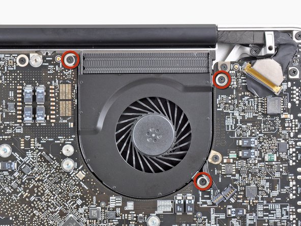
Use the flat end of a spudger to lift the left fan connector out of its socket on the logic board.
-
-
-
Use the tip of a spudger or your fingernail to flip up the retaining flap on the keyboard backlight ribbon cable.
-
Pull the keyboard backlight ribbon cable out of its socket.
On my early 2011 Macbook Pro unibody 17” - there is another small cable to disconnect between this, the keyboard backlight ribbon cable and the optical drive cable. Not sure what it’s for, but thought to mention is. It is small metal plug and socket and says “AC” on it.
-
-
-
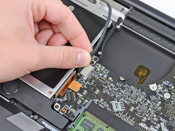
Use the tip of a spudger to push the small plastic cable retainer away from the camera cable socket for enough clearance to remove the camera cable.
Bit of a levering horizontally. Remove the carbon fibre patterned tape off the top of the connector to expose the connector then slide (break the adhesive bond) on the small oblong black plastic passed, towards the optical drive module. The connector can then be disengaged. It's quite difficult to unlatch the connector! Take extreme care
not on my 17” late 2011
On my late 2011 MBP there are two connectors at this place: One big connector like the silver one shown on the fotos (but in my case it is black), and the tiny one as discribed in the comment from anon 10/14/2017). In contrast to the fotos, this tiny connector is on the opposite side of the big one, on the edge close to the right fan. To disconnect this connector, follow the instructions from anon 10/14/2017.
The cable going to the big connector is in my case a wide black ribbon cable running diagonically over the optical drive. To remove the connector of this cable from the socket, pry it upwards carefully with your fingernails or a spudger.
-
-
-
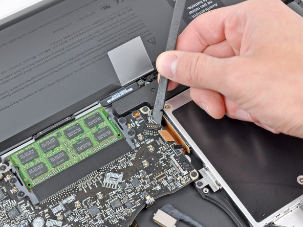
Pull the camera cable toward the optical drive opening to disconnect it from the logic board.
This step and the previous one (plastic retainer) were very different on my logic board. It's an early 2011, 17" that I bought second hand. I'm wondering if the logic board was previously replaced.
-
-
-
-
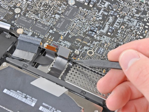
Use the tip of a spudger or your fingernail to flip up the retaining flap on the IR sensor ribbon cable socket.
-
Pull the IR sensor ribbon cable out of its socket.
The IR sensor cable also connects the Hall Effect switch that detects whether the lid is closed or open (and thus shuts off the display, puts the computer to sleep, wakes it up, etc.) to the logic board.
How do I know? I re-pasted my late 2011 17" MBP and forgot to reconnect it. The machine would not sleep automatically when the lid was closed anymore. Re-connecting the cable fixed it.
thanks for the info !!!! i got the same problem with sleep because the cable was not properly connected
-
-
-
Remove the following four screws:
-
Two 3.5 mm Phillips screws
-
Two 1.6 mm Phillips screws
-
Remove both connector shields from the logic board.
On my early 2011 laptop, the screws on the left hand shield were T6 screws. The others were Phillips head.
The same applies to the late 2011 model.
on my early 2011 model it seems that on the left hand shield (with the Torx screws) the track pad connector is stuck to the underside of the connector. It lifted off the logic board when I tried to remove the shield and I am leaving it like that until I can manage to access it better - maybe when the logic board is out.
-
-
-
Use your fingernail to flip up the retaining flap on the keyboard ribbon cable socket.
-
Pull the keyboard ribbon cable out of its socket.
Thanks for the great guide!
Tip for re-seating the keyboard cable: put a piece of sticky tape on, fold over at the top end, re-seat the connector (carefully!) with a spudger and (gently!) pull the tape 'over' the connector on the logic board until you feel it nudges in fully. Notice the emphasis on "carefully" and "gently"... :)
Thanks for this manual! I used it to replace the keyboard. I would not recommend it as an easy job and it is not described on Ifixit for unknown reasons. But I did it and everytinhg worked fine. 2 remarks about the conncetion for the keyboard. In my Macbook 17 Pro (mid 2009) there is a litlle lever that clamps the keyboard 'cable'. You can get it out easily (I did that too because I did not see it then), but to reassemble it it is better to uplift the little lever and then move the 'cable' in with sticky tape (thanks for that tip!)
I had to redo it 3 times to get it working. With the lever up and then clamping the 'cable' by pushing it down it worked AND it solved the power button problem. Please be carefull as said in the manual, it is all very delicate!
And for replacing the keyboard; prepare yourself for a lot of tiny screws! (some of them are stuck and had to be removed with force, be warned!)
Another tip
-
-
-
Use your fingernail to flip up the retaining flap on the express card cage ribbon cable socket.
-
Pull the express card cage ribbon cable out of its socket.
It might be easier to remove the ExpressCard ribbon cable in Step 18 by removing the Hard Drive cable first...use your judgment.
-
-
-
Use the tip of a spudger or your fingernail to flip up the retaining flap on the battery indicator cable socket.
-
Pull the battery indicator ribbon cable out of its socket.
When reassembling, slide the ribbon cable underneath the connector then lock it into place.
-
-
-
Lift the black plastic flap attached to the display data cable retainer and rotate it toward the DC-In side of the MacBook.
-
Pull the display data cable out of its socket.
Be SUPER EXTRA CAREFUL when connecting this cable back!!! Use a magnifying glass or headset to see what you are doing.
When I plugged it in the first time (finished the rest of the process and restarted the mac) I got green lines all over my screen…
I replugged it a total of 4 times to get it right even cleaned it with alcohol. Now everything is working, but I freaked out a bit :)
I would describe the removal as “sliding back towards the corner". “Pulling out", to me, implies pulling up away from the board.
When reassembling, slide the cable underneath the connector. It doesn’t snap on.
This is the trickiest step in this whole process, both detaching and reattaching. I’ve been through this logic board repair scenario with my Early 2011 about 4x now, and if, when you reassemble, you’re still having problems with your display of any sort, this is your number 1 achilles heel is this connector getting dirty (use high purity over 90% isopropyl alcohol often found at drug stores next to the regular 70% stuff for cleaning) or not seating properly. I have broken off the connector bracket mount that goes over the top but was able to use pure silicone to safely reattach it. Don’t break that top bracket off sliding this puppy out; it’s a very dicey situation!
I had no idea what "toward the DC-in side" meant. "DC-in" refers to the Magsafe connector/port in the corner of the machine (upper right when the machine is facedown with lower case removed).
The plastic flap and its little metal bracket broke off from the cable when I tried to rotate it out of the socket. Will this cause problems? I'm assuming it was just a handle. I was successfully able to slide the cable out, and then back into the socket on reassembly, even after the bracket/tab broke off.
-
-
-
Remove the following eight screws securing the logic board and DC-In board to the upper case:
-
Six 3.2 mm Phillips screws
-
Two 7.6 mm Phillips screws
The Six 3.2mm screws can in some cases be torx instead of phillips
I've got a great idea for keeping the tiny screws safe and also labelled up e.g. these 6+2 screws belong to the logic board - simply use 'Post-It' sticky note upside down on your desk and use the sticky bit to keep the screws from rolling around getting themselves lost :-)
-
-
-
Lift the logic board assembly from the side nearest the optical drive and lift it away from the upper case.
-
Carefully pull the ports and DC-In board away from the side of the upper case and remove the logic board assembly, minding any cables that may get caught.
When lifting the logic board be careful! The rubber foam around the microphone may have adhered the microphone to the uppercases grill work so as you lift you could rip the connector from the ribbon cable.
* Take a small spatula and thought the fan opening carefully dislodge the microphone from the grill as you lift the logic board.
* To locate the microphone note on the next slide the small unit between the fingers of the hands.
Attach the DC connector with screws first when reassembling.
-


To reassemble your device, follow these instructions in reverse order.
To reassemble your device, follow these instructions in reverse order.

On my 2011 MBP, the wiring is twisted a half turn. Its not possible to insert the connector the wrong way around, but it just seems sloppy that it was designed to require stressing the wire this way.
anon - Contestar