Saltar al contenido principal

Esta versión puede contener ediciones incorrectas. Cambie a la última instantánea verificada.

Qué necesitas

  1. , Carcasa inferior: paso 1, imagen 1 de 1
    • Retira los diez tornillos que aseguran la carcasa inferior al ordenador:

    • Tres tornillos Phillips de 13.5 mm

    • Siete tornillos Phillips de 3 mm.

  2. : paso 2, imagen 1 de 2 : paso 2, imagen 2 de 2
    • Introduce los dedos entre la carcasa inferior y la rejilla de ventilación, y levántala para liberar los dos clips que sujetan la carcasa inferior a la superior.

    • Durante el reensamblaje, alinea cuidadosamente la carcasa inferior y luego presiónela firmemente hasta que ambos clips encajen.

    • Retira la carcasa superior

  3. , Batería: paso 3, imagen 1 de 3 , Batería: paso 3, imagen 2 de 3 , Batería: paso 3, imagen 3 de 3
    • Siempre que se trabaje cerca de la placa lógica, conviene desconectar primero la batería para evitar cortocircuitos.

    • Si está presente, agarre la lengüeta de plástico unida al conector de la batería y tire de ella hacia el borde frontal del dispositivo. En los modelos Late-2011, el conector de la batería no tiene lengüeta y es simplemente un enchufe que se inserta directamente en la placa base.

    • Si falta la lengüeta de plástico, utiliza un spudger para levantar el conector de su alojamiento.

    • Tira de la lengüeta en paralelo a la cara de la placa lógica.

  4. Este paso está sin traducir. Ayuda a traducirlo

    : paso 4, imagen 1 de 3 : paso 4, imagen 2 de 3 : paso 4, imagen 3 de 3
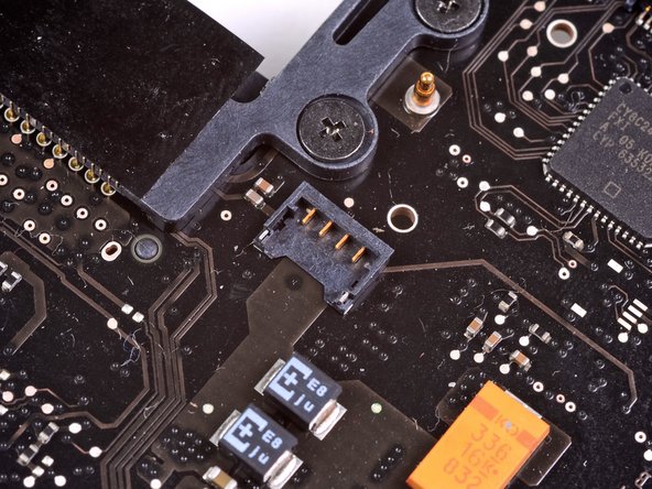
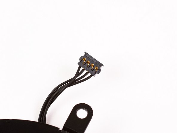
    • Use the flat end of a spudger to lift the left fan connector out of its socket on the logic board.

    • It is useful to twist the spudger axially from beneath the fan cable wires to release the connector.

    • The fan socket and the fan connector can be seen in the second and third pictures. Be careful not to break the plastic fan socket off the logic board as you use your spudger to lift the fan connector straight up and out of its socket. The layout of the logic board shown in the second picture may look slightly different than your machine but the fan socket is the same.

  5. Este paso está sin traducir. Ayuda a traducirlo

    : paso 5, imagen 1 de 1
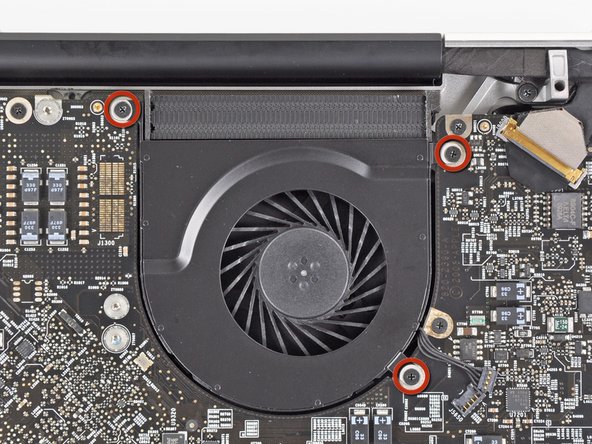
    • Remove the three 3.1 mm Phillips screws securing the left fan to the logic board.

    • In the Late 2011 MacBook Pro 17" Unibody these screws will be T6 Torx.

  6. Este paso está sin traducir. Ayuda a traducirlo

    : paso 6, imagen 1 de 1
    • Remove the left fan from the upper case, minding its cable that may get caught.

Linea de Meta

32 personas más completaron esta guía.

2 comentarios

As long as I had the machine open for the battery, made sense to replace the fans. I had forgot how quite my MacBook Pro was, until I put the new fans in. Thanks ifixit!!

Leo Lambert Jr - Contestar

I had a few problems with the fan cables!!!

Moritz Ascherl - Contestar

Agregar Comentario

Ver Estadísticas:

Ultimas 24 horas: 1

Ultimos 7 días: 15

Ultimos 30 días: 31

Todo El Tiempo: 23,658