Esta versión puede contener ediciones incorrectas. Cambiar a la última instantánea verificada.
Qué necesitas
-
-
Retira los diez tornillos que aseguran la carcasa inferior al ordenador:
-
Tres tornillos Phillips de 13.5 mm
-
Siete tornillos Phillips de 3 mm.
-
-
-
Si está presente, agarre la lengüeta de plástico unida al conector de la batería y tire de ella hacia el borde frontal del dispositivo. En los modelos Late-2011, el conector de la batería no tiene lengüeta y es simplemente un enchufe que se inserta directamente en la placa base.
-
-
Este paso está sin traducir. Ayuda a traducirlo
-
Use the tip of a spudger to push the small plastic cable retainer away from the camera cable socket for enough clearance to remove the camera cable.
-
-
Este paso está sin traducir. Ayuda a traducirlo
-
Pull the camera cable toward the optical drive opening to disconnect it from the logic board.
-
-
Este paso está sin traducir. Ayuda a traducirlo
-
Carefully pull the Bluetooth cable toward the fans to disconnect it from the Bluetooth board.
-
-
Este paso está sin traducir. Ayuda a traducirlo
-
Use the flat end of a spudger to peel the thin plastic cover off the top and sides of the Bluetooth board housing. For late-2011 models check out the other picture because the connector location is in a totally different location.
-
-
Este paso está sin traducir. Ayuda a traducirlo
-
Use the flat end of a spudger to pry the Bluetooth antenna connector up and off its socket on the Bluetooth board.
-
-
-
Este paso está sin traducir. Ayuda a traducirlo
-
De-route the camera cable from the slot molded into the Bluetooth board housing.
-
-
Este paso está sin traducir. Ayuda a traducirlo
-
Remove the two 7.1 mm Phillips screws securing the camera cable retainer to the upper case.
-
Remove the camera cable retainer from the upper case.
-
-
Este paso está sin traducir. Ayuda a traducirlo
-
Lift the black plastic flap attached to the display data cable retainer and rotate it toward the DC-In side of the MacBook.
-
Pull the display data cable out of its socket.
-
-
Este paso está sin traducir. Ayuda a traducirlo
-
Remove the two 7.1 mm Phillips screws securing the display data cable retainer to the upper case.
-
Remove the display data cable retainer.
-
-
Este paso está sin traducir. Ayuda a traducirlo
-
Remove the two outer 6.8 mm T6 Torx screws from each of the two display brackets (four screws total).
-
-
Este paso está sin traducir. Ayuda a traducirlo
-
While holding the display and upper case together with your left hand, remove the remaining T6 Torx screw from the lower display bracket.
-
-
Este paso está sin traducir. Ayuda a traducirlo
-
Remove the last remaining T6 Torx screw securing the display to the upper case.
-
-
Este paso está sin traducir. Ayuda a traducirlo
-
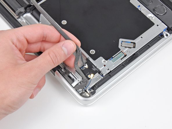
Grab the upper case with your right hand and rotate it slightly toward the top of the display so the upper display bracket clears the edge of the upper case.
-
Rotate the display slightly away from the upper case.
-
Lift the display up and away from the upper case, minding any brackets or cables that may get caught.
-
-
Este paso está sin traducir. Ayuda a traducirlo
-
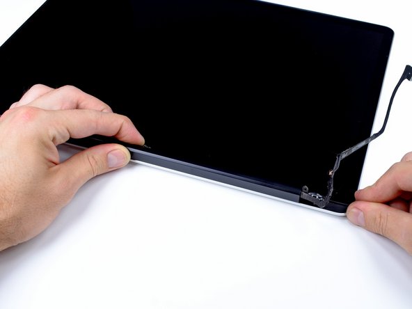
Grab the clutch cover as shown and slide it toward the right side of the display.
-
-
Este paso está sin traducir. Ayuda a traducirlo
-
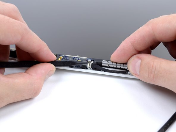
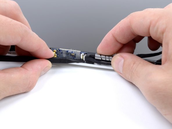
Lifting the left edge of the clutch cover, gently rock it back and forth on its long axis while pulling it away from the display.
-
Remove the clutch cover from the display, minding any cables that may get caught.
-
-
Este paso está sin traducir. Ayuda a traducirlo
-
Use the tip of a spudger to disconnect the two antenna cable connectors from the AirPort board.
-
-
Este paso está sin traducir. Ayuda a traducirlo
-
Remove the single 2.7 mm Phillips #00 screw securing the AirPort board bracket to the display case.
-
-
Este paso está sin traducir. Ayuda a traducirlo
-
Move the AirPort board bracket towards the bottom of the display case with the tip of a spudger so that it does not block the AirPort board cable.
-
Use the tip of a spudger to disconnect the AirPort board cable by rocking it back and forth until it is free.
-
-
Este paso está sin traducir. Ayuda a traducirlo
-
Once the cable is disconnected, lift and remove the plastic bracket from the display case.
-
-
Este paso está sin traducir. Ayuda a traducirlo
-
Remove the two 3.1 mm Phillips #00 screws securing the AirPort board to the display case.
-
-
Este paso está sin traducir. Ayuda a traducirlo
-
Lift and remove the AirPort board from the display case.
-


Cancelar: No complete esta guía.
15 personas más completaron esta guía.


6 comentarios
Just a note for anyone looking at this guide with a MacBook Pro 17" mid 2010 model (2.6GHz) - this is the wrong guide for your laptop! Search for the MacBook Pro 15" mid 2010 Airport board replacement guide instead. The card is located on top of the optical drive rather than in the bezel - something i found out the hard way when following this ;)
THIS GUIDE IS WRONG FOR MODEL 1297, which is far easier to repair.
HI Kevin. Do you know a URL to a good video for the 1297?