Esta versión puede contener ediciones incorrectas. Cambiar a la última instantánea verificada.
Qué necesitas
-
-
Remueve los siguientes diez tornillos que aseguran la cubierta trasera a la cubierta superior.
-
Tres tornillos tipo Philips (punta cruz) de 13.5 mm (14.1 mm)
-
Cuando remuevas estos tornillos, ten en cuenta cómo salen en un ángulo ligero. Deben volverse a instalar de igual forma.
-
-
-
Retira los dos tornillos de punto triple de 7.4 mm que sujetan la batería a la caja superior.
-
Nota: Para ciertas reparaciones (por ejemplo, disco duro), no es necesario quitar la batería, pero evita cualquier cortocircuito accidental de los componentes electrónicos en la placa base. Si no quitas la batería, ten cuidado ya que las partes de la placa pueden estar electrificadas.
-
-
-
Inclina la batería fuera de la placa lógica lo suficiente para acceder al conector del cable de la batería.
-
Extrae el conector del cable de la batería de su zócalo en la placa lógica y extrae a la batería de la carcasa superior.
-
Cárgala al 100 % y luego sigue cargándola durante al menos 2 horas. Luego, desenchúfala y úsala para drenar la batería. Cuando veas la advertencia de batería baja, guarda tu trabajo y mantén tu computadora portátil encendida hasta que se apague por batería baja. Espera al menos cinco horas, luego carga tu portátil ininterrumpidamente hasta 100%.
-
Si notas algún comportamiento inusual o problemas luego de instalar tu batería nueva, podría necesitar restablecer el controlador de gestión de sistema de tu MacBook.
-
-
-
Remueve los tres tornillos de torsión T6 de 3.4 mm (3.1 mm) que aseguran el disipador izquierdo a la tarjeta madre
-
-
Este paso está sin traducir. Ayuda a traducirlo
-
Remove the three T6 Torx screws securing the right fan to the upper case.
-
-
-
Este paso está sin traducir. Ayuda a traducirlo
-
Use the flat end of a spudger to pry the right fan connector up out of its socket on the logic board.
-
Remove the right fan from the upper case.
-
-
Este paso está sin traducir. Ayuda a traducirlo
-
Use the flat end of a spudger to pry the AirPort / Bluetooth ribbon cable up off its socket on the logic board.
-
-
Este paso está sin traducir. Ayuda a traducirlo
-
Disconnect the iSight cable by pulling its connector toward the optical drive opening.
-
-
Este paso está sin traducir. Ayuda a traducirlo
-
Use the flat end of a spudger to pry the optical drive cable connector up from the logic board.
-
-
Este paso está sin traducir. Ayuda a traducirlo
-
Carefully pull the subwoofer/right speaker cable up to lift its connector out of its socket on the logic board.
-
-
Este paso está sin traducir. Ayuda a traducirlo
-
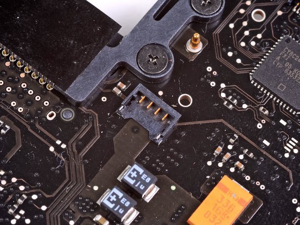
Use the flat end of a spudger to pry the hard drive cable connector up out of its socket on the logic board.
-
-
Este paso está sin traducir. Ayuda a traducirlo
-
Remove the two short Phillips screws securing the small EMI shield to the logic board.
-
Remove the EMI shield from the logic board.
-
-
Este paso está sin traducir. Ayuda a traducirlo
-
Use the flat end of a spudger to pry the trackpad cable connector up out of its socket on the logic board.
-
-
Este paso está sin traducir. Ayuda a traducirlo
-
Use your fingernail to carefully flip up the keyboard ribbon cable retaining flap.
-
Use the tip of a spudger to pull the keyboard ribbon cable straight out of its socket.
-
-
Este paso está sin traducir. Ayuda a traducirlo
-
Use the flat end of a spudger to pry the battery indicator cable connector up out of its socket on the logic board.
-
-
Este paso está sin traducir. Ayuda a traducirlo
-
Grab the plastic pull tab secured to the display data cable lock and rotate it toward the DC-In side of the computer.
-
Pull the display data cable straight out of its socket.
-
-
Este paso está sin traducir. Ayuda a traducirlo
-
Use the tip of a spudger or your fingernail to flip up the retaining flap on the keyboard backlight ribbon cable socket.
-
Pull the keyboard ribbon cable straight out of its socket.
-
-
Este paso está sin traducir. Ayuda a traducirlo
-
Remove the following screws:
-
Seven 3.3 mm T6 Torx screws securing the logic board to the upper case.
-
Two 8 mm T6 Torx screws securing the DC-In board to the upper case.
-
-
Este paso está sin traducir. Ayuda a traducirlo
-
Carefully lift the logic board assembly from the left side and work it out of the upper case, minding the port side that may get caught during removal.
-
-
Este paso está sin traducir. Ayuda a traducirlo
-
Lift the logic board enough to gain clearance and use a spudger to pry the microphone up off the upper case.
-
-
Este paso está sin traducir. Ayuda a traducirlo
-
Slide the logic board away from the port openings and lift the assembly out of the upper case.
-
-
Este paso está sin traducir. Ayuda a traducirlo
-
Remove the two 5 mm Phillips screws securing the left speaker to the logic board.
-
-
Este paso está sin traducir. Ayuda a traducirlo
-
Carefully pull the left speaker wires upward to lift the left speaker connector out of its socket on the logic board.
-


Cancelar: No complete esta guía.
13 personas más completaron esta guía.

2 comentarios
I changed the left speaker with another one got on ebay. but still it has refused to work. what other methods can i try?
Stellar guide, easier than it looks at first, new left speaker from China, perfect sound once again in this 11-year old MBP.