Saltar al contenido principal

Esta versión puede contener ediciones incorrectas. Cambie a la última instantánea verificada.

Qué necesitas

  1. , Caja inferior: paso 1, imagen 1 de 1
    • Remueve los siguientes diez tornillos que sujetan la caja inferior de la caja a la caja superior:

    • Siete tornillos Phillips de 3 mm.

    • Tres tornillos Phillips de 13.5 mm.

  2. : paso 2, imagen 1 de 2 : paso 2, imagen 2 de 2
    • Con ambas manos, levanta la pequeña caja cerca de la rejilla de ventilación para sacarla de dos clips que la sujetan a la caja superior.

    • Retira la caja pequeña y déjala a un lado.

  3. , Batería: paso 3, imagen 1 de 1
    Herramienta utilizada en este paso:
    P6 Pentalobe Screwdriver 2009 15" MacBook Pro Battery
    $5.49
    Comprar
    • Retira los dos tornillos de Pentalobe de 5 puntos a lo largo del borde superior de la batería.

    • No es necesario seguir los pasos 3 a 6 para extraer la batería y reemplazar el disco duro. Sin embargo, se recomienda eliminar todas las fuentes de alimentación de la electrónica antes de trabajar en ellas.

  4. : paso 4, imagen 1 de 1
    • Usa la punta de un spudger para doblar hacia atrás el dedo de la etiqueta "Advertencia: No quitar la batería" mientras quitas el tercer tornillo Pentalobe de cinco puntos escondido debajo.

  5. : paso 5, imagen 1 de 2 : paso 5, imagen 2 de 2
    • Levanta la batería con su lengüeta de plástico y deslízala hacia afuera desde el borde largo de la caja superior.

    • No intentes eliminar completamente la batería por el momento.

  6. : paso 6, imagen 1 de 1
    • Inclina la batería hacia atrás lo suficiente para acceder al conector del cable de la batería.

    • Extrae el conector del cable de la batería de su zócalo en la placa lógica y extrae la batería de la carcasa superior.

    • Si estás instalando una batería nueva, debes calibrarla luego de la instalación.

  7. Este paso está sin traducir. Ayuda a traducirlo

    : paso 7, imagen 1 de 1
    • Apple sticks a small strip of clear plastic with adhesive applied to one side of the logic board behind the camera cable connector to keep it in its socket. When moving it out of the way, be sure not to break any surface-mount components off the logic board.

    • Use the tip of a spudger to rotate the plastic retainer away from the camera cable connector.

  8. Este paso está sin traducir. Ayuda a traducirlo

    : paso 8, imagen 1 de 2 : paso 8, imagen 2 de 2
    • Pull the camera cable away from its socket on the logic board.

    • Pull the connector parallel to the face of the logic board, not straight up.

  9. Este paso está sin traducir. Ayuda a traducirlo

    : paso 9, imagen 1 de 1
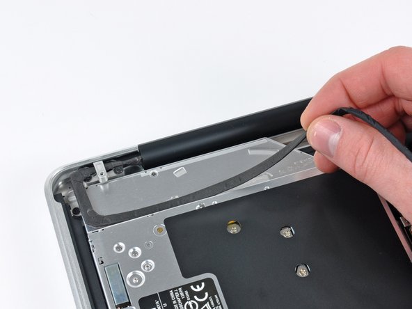
    • Peel the camera cable off the adhesive securing it to the body of the optical drive.

  10. Este paso está sin traducir. Ayuda a traducirlo

    : paso 10, imagen 1 de 2 : paso 10, imagen 2 de 2
    • This step is only required if you have an anti-glare display. If you have a glossy display, skip to step 12.

    • Disconnect the Bluetooth cable by pulling the male end straight away from its socket.

    • Pull the connector parallel to the face of the logic board, not straight up.

    • Use the flat end of a spudger to pry the Bluetooth antenna cable up from its socket on the board.

  11. Este paso está sin traducir. Ayuda a traducirlo

    : paso 11, imagen 1 de 2 : paso 11, imagen 2 de 2
    • This step is only required if you have an anti-glare display.

    • Remove the two 8 mm Phillips screws securing the Bluetooth/camera cable retainer to the upper case.

    • One of the screws may remain captive in the Bluetooth/camera cable ground loop. If replacing the display, be sure to transfer this screw to the new unit.

    • Lift the Bluetooth board/cable retainer assembly out of the upper case.

  12. Este paso está sin traducir. Ayuda a traducirlo

    : paso 12, imagen 1 de 2 : paso 12, imagen 2 de 2
    • This step is only for glossy display machines. If you have an anti-glare display, skip this step.

    • Remove the two 8 mm Phillips screws securing the camera cable retainer to the upper case.

    • One of the screws may remain captive in the camera cable ground loop. If replacing the display, be sure to transfer this screw to the new unit.

    • Lift the camera cable retainer out of the upper case.

  13. Este paso está sin traducir. Ayuda a traducirlo

    : paso 13, imagen 1 de 2 : paso 13, imagen 2 de 2
    • Grab the plastic pull tab secured to the display data cable lock and rotate it toward the DC-In side of the computer.

  14. Este paso está sin traducir. Ayuda a traducirlo

    : paso 14, imagen 1 de 2 : paso 14, imagen 2 de 2
    • Remove the single 7 mm Phillips screw securing the display data cable retainer to the upper case.

    • This screw may remain captive in the display data cable ground loop. If replacing the display, be sure to transfer this screw to the new unit.

    • Remove the display data cable retainer from the upper case.

  15. Este paso está sin traducir. Ayuda a traducirlo

    : paso 15, imagen 1 de 1
    • Be sure the display data cable lock is rotated toward the DC-In board before proceeding.

    • Pull the display data cable connector straight away from its socket.

    • Make sure to pull the connector parallel to the face of the logic board, not straight up from its socket.

  16. Este paso está sin traducir. Ayuda a traducirlo

    : paso 16, imagen 1 de 2 : paso 16, imagen 2 de 2
    • Remove the outer two T6 Torx screws securing both display hinges to the upper case (four screws total).

  17. Este paso está sin traducir. Ayuda a traducirlo

    : paso 17, imagen 1 de 1
    • Open your MacBook Pro so the display is perpendicular to the upper case.

    • Place your opened MacBook Pro on a table as pictured.

    • While holding the display and upper case together with your left hand, remove the remaining T6 Torx screw from the lower display bracket.

  18. Este paso está sin traducir. Ayuda a traducirlo

    : paso 18, imagen 1 de 1
    • Be sure to hold the display and upper case together with your left hand. Failure to do so may cause the freed display/upper case to fall, potentially damaging each component.

    • Remove the last remaining T6 Torx screw securing the display to the upper case.

  19. Este paso está sin traducir. Ayuda a traducirlo

    : paso 19, imagen 1 de 3 : paso 19, imagen 2 de 3 : paso 19, imagen 3 de 3
    • Grab the upper case with your right hand and rotate it slightly toward the top of the display so the upper display bracket clears the edge of the upper case.

    • Rotate the display slightly away from the upper case.

    • Lift the display up and away from the upper case, minding any brackets or cables that may get caught.

Linea de Meta

43 personas más completaron esta guía.

0 comentarios

Agregar Comentario

Ver Estadísticas:

Ultimas 24 horas: 4

Ultimos 7 días: 15

Ultimos 30 días: 42

Todo El Tiempo: 45,689