Esta versión puede contener ediciones incorrectas. Cambie a la última instantánea verificada.
Qué necesitas
-
-
Remueve los siguientes diez tornillos que aseguran la cubierta trasera a la cubierta superior.
-
Tres tornillos tipo Philips (punta cruz) de 13.5 mm (14.1 mm)
-
Cuando remuevas estos tornillos, ten en cuenta cómo salen en un ángulo ligero. Deben volverse a instalar de igual forma.
-
-
-
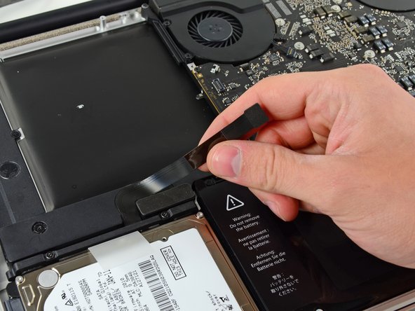
Usa el borde del spudger para apalancar el conector de la batería hacia arriba del enchufe en la tarjeta lógica.
-
-
-
Desconecta el conector del cable de la cámara de su zócalo en la placa lógica.
-
-
-
Este paso está sin traducir. Ayuda a traducirlo
-
Use the flat end of a spudger to pry the hard drive/IR sensor cable connector up off the logic board.
-
Peel the hard drive cable up from the channel within the subwoofer and right speaker.
-
-
Este paso está sin traducir. Ayuda a traducirlo
-
Using the flat end of a spudger, pry the subwoofer connector straight up off the logic board.
-
-
Este paso está sin traducir. Ayuda a traducirlo
-
Remove the following six screws securing the subwoofer and right speaker to the upper case:
-
Two 3.2 mm Phillips screws.
-
Two 12.3 mm Phillips screws.
-
One 2.5 mm Phillips screw.
-
One 8.3 mm Phillips screw.
-
-
Este paso está sin traducir. Ayuda a traducirlo
-
Use the flat end of a spudger to dislodge the right speaker from its recess in the upper case.
-
Lift the subwoofer and right speaker assembly out of the upper case.
-


Cancelar: No complete esta guía.
4 personas más completaron esta guía.
