Esta versión puede contener ediciones incorrectas. Cambie a la última instantánea verificada.
Qué necesitas
-
Este paso está sin traducir. Ayuda a traducirlo
-
Disconnect the camera cable by pulling the male end straight away from its socket.
-
-
Este paso está sin traducir. Ayuda a traducirlo
-
Deroute the camera data cable from the channel in the optical drive.
-
-
-
Este paso está sin traducir. Ayuda a traducirlo
-
Use a spudger to pry the optical drive connector straight up off the logic board.
-
-
Este paso está sin traducir. Ayuda a traducirlo
-
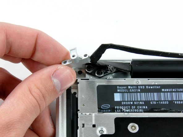
Remove two 8 mm Phillips screws securing the camera cable bracket to the upper case.
-
Lift the camera cable bracket out from the upper case.
-
-
Este paso está sin traducir. Ayuda a traducirlo
-
Remove the following three Phillips screws securing the optical drive to the upper case:
-
One 3.5 mm Phillips screw.
-
Two 2.5 mm Phillips screws.
-
-
Este paso está sin traducir. Ayuda a traducirlo
-
Lift the optical drive from its left edge and pull it out of the computer.
-