Esta versión puede contener ediciones incorrectas. Cambie a la última instantánea verificada.
Qué necesitas
-
-
Con el estuche cerrado, coloca el Unibody boca arriba sobre una superficie plana.
-
Presiona el lado ranurado del pestillo de liberación de la puerta de acceso lo suficiente para agarrar el extremo libre. Levanta el pestillo de liberación hasta que quede vertical.
-
-
-
Agarra la lengüeta de plástico translúcido y extrae la batería de la Unibody.
-
Si se presiona el pestillo, se bloqueará la batería en su lugar.
-
-
-
Retira los siguientes ocho tornillos que sujetan la carcasa inferior al chasis:
-
Un tornillo Phillips de 5.4 mm.
-
Tres tornillos Phillips de 14 mm.
-
Cuatro tornillos Phillips de 3.5 mm.
-
-
Este paso está sin traducir. Ayuda a traducirlo
-
Disconnect the camera cable by pulling the male end straight away from its socket.
-
-
Este paso está sin traducir. Ayuda a traducirlo
-
Deroute the camera data cable from the channel in the optical drive.
-
-
-
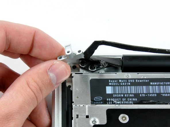
Este paso está sin traducir. Ayuda a traducirlo
-
Use a spudger to pry the optical drive connector straight up off the logic board.
-
-
Este paso está sin traducir. Ayuda a traducirlo
-
Remove two 8 mm Phillips screws securing the camera cable bracket to the upper case.
-
Lift the camera cable bracket out from the upper case.
-
-
Este paso está sin traducir. Ayuda a traducirlo
-
Remove the following three Phillips screws securing the optical drive to the upper case:
-
One 3.5 mm Phillips screw.
-
Two 2.5 mm Phillips screws.
-
-
Este paso está sin traducir. Ayuda a traducirlo
-
Lift the optical drive from its left edge and pull it out of the computer.
-
-
Este paso está sin traducir. Ayuda a traducirlo
-
Using the flat end of a spudger, pry the subwoofer connector straight up off the logic board.
-
-
Este paso está sin traducir. Ayuda a traducirlo
-
Remove the following four screws securing the subwoofer and right speaker to the upper case:
-
Two 3.2 mm Phillips screws.
-
One 2.6 mm Phillips screw.
-
One 5 mm Phillips screw.
-
-
Este paso está sin traducir. Ayuda a traducirlo
-
Lift the subwoofer and right speaker assembly out of the upper case.
-
-
Este paso está sin traducir. Ayuda a traducirlo
-
Remove the single Phillips screw securing the hard drive bracket to the upper case.
-
-
Este paso está sin traducir. Ayuda a traducirlo
-
Lift the hard drive by its plastic pull tab and remove the freed hard drive bracket.
-
-
Este paso está sin traducir. Ayuda a traducirlo
-
Lift the hard drive out of its supports and disconnect the SATA cable by pulling the connector straight away from the hard drive.
-
-
Este paso está sin traducir. Ayuda a traducirlo
-
Remove the following 5 screws securing the mid wall to the upper case:
-
Three 10.5 mm Phillips screws.
-
Two 3.7 mm Phillips screws.
-
Lift the mid wall out of the upper case.
-
-
Este paso está sin traducir. Ayuda a traducirlo
-
Use a spudger to pry the hard drive cable connector straight up off the logic board.
-
-
Este paso está sin traducir. Ayuda a traducirlo
-
Peel the hard drive cable from the adhesive securing it to the upper case, and maneuver the plastic retaining block out of the upper case.
-


Cancelar: No complete esta guía.
9 personas más completaron esta guía.

Un comentario
great explanation I was looking for instruction on YouTube but with no luck thank you so much !!!