Esta versión puede contener ediciones incorrectas. Cambiar a la última instantánea verificada.
Qué necesitas
-
-
Remueve los siguientes diez tornillos que aseguran la cubierta trasera a la cubierta superior.
-
Tres tornillos tipo Philips (punta cruz) de 13.5 mm (14.1 mm)
-
Cuando remuevas estos tornillos, ten en cuenta cómo salen en un ángulo ligero. Deben volverse a instalar de igual forma.
-
-
-
Usa el borde del spudger para apalancar el conector de la batería hacia arriba del enchufe en la tarjeta lógica.
-
-
-
Retire los siguientes tres tornillos que sujetan el ventilador izquierdo a la placa lógica:
-
Dos tornillos Torx T6 de 3,5 mm.
-
Un tornillo Torx T6 de 4,2 mm.
-
-
Este paso está sin traducir. Ayuda a traducirlo
-
Use the flat end of a spudger to lift the right fan connector out of its socket on the logic board.
-
-
Este paso está sin traducir. Ayuda a traducirlo
-
Remove the three 3.4 mm (3.1 mm) T6 Torx screws securing the right fan to the logic board.
-
Lift the right fan out of its opening in the logic board.
-
-
Este paso está sin traducir. Ayuda a traducirlo
-
Pull the camera cable out of its socket on the logic board.
-
-
-
Este paso está sin traducir. Ayuda a traducirlo
-
Use the flat end of a spudger to pry the AirPort/Bluetooth connector up from its socket on the logic board.
-
-
Este paso está sin traducir. Ayuda a traducirlo
-
Use the flat end of a spudger to lift the optical drive connector out of its socket on the logic board.
-
-
Este paso está sin traducir. Ayuda a traducirlo
-
Disconnect the hard drive/IR sensor cable from its socket on the logic board by lifting up from beneath its connector.
-
-
Este paso está sin traducir. Ayuda a traducirlo
-
Use the flat end of a spudger to lift the subwoofer/right speaker connector out of its socket on the logic board.
-
-
Este paso está sin traducir. Ayuda a traducirlo
-
Use the flat end of a spudger to pry the trackpad connector up and out of its socket on the logic board.
-
-
Este paso está sin traducir. Ayuda a traducirlo
-
Use your fingernail to flip up the retaining flap on the keyboard ribbon cable ZIF socket.
-
Use the tip of a spudger to pull the keyboard ribbon cable out of its socket.
-
-
Este paso está sin traducir. Ayuda a traducirlo
-
Use the flat end of a spudger to lift the battery indicator connector up and out of its socket on the logic board.
-
-
Este paso está sin traducir. Ayuda a traducirlo
-
Grab the plastic pull tab secured to the display data cable lock and rotate it toward the DC-In side of the computer.
-
Pull the display data cable straight out of its socket on the logic board.
-
-
Este paso está sin traducir. Ayuda a traducirlo
-
Use the tip of a spudger to flip up the retaining flap on the keyboard backlight ribbon cable ZIF socket.
-
Pull the keyboard backlight ribbon cable out of its socket.
-
-
Este paso está sin traducir. Ayuda a traducirlo
-
Remove the following nine screws:
-
Seven 3.4 mm ( 3.1 mm) T6 Torx screws on the logic board
-
Two 8 mm T6 Torx screws on the DC-In board
-
-
Este paso está sin traducir. Ayuda a traducirlo
-
Carefully lift the logic board assembly from its left side and work it out of the upper case, minding the optical drive cable and the I/O ports that may get caught during removal.
-
If necessary, use the flat end of a spudger to separate the microphone from the upper case.
-
Pull the I/O port side of the logic board away from the side of the upper case and remove the logic board assembly.
-
-
Este paso está sin traducir. Ayuda a traducirlo
-
Remove the two 7.5 mm ( 7.2 mm )Tri-point screws securing the battery to the upper case.
-
-
Este paso está sin traducir. Ayuda a traducirlo
-
Carefully peel the battery warning label off the upper case between the battery and the optical drive to reveal an additional Tri-point screw.
-
Remove the last 7.5 mm ( 7.2 mm ) Tri-point screw securing the battery to the upper case.
-
-
Este paso está sin traducir. Ayuda a traducirlo
-
Use the attached plastic pull tab to remove the battery from the upper case.
-
-
Este paso está sin traducir. Ayuda a traducirlo
-
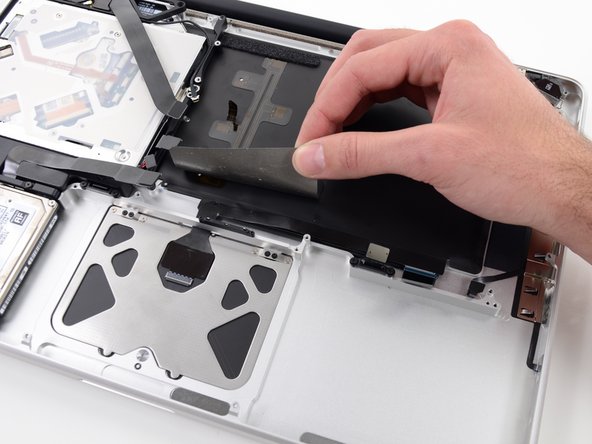
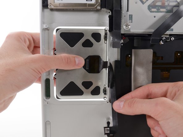
Use the flat end of a spudger to peel up the edge of the large piece of black tape covering the trackpad cable.
-
Peel the tape up and fold it back out of the way of the trackpad cable. Leaving it in place on the upper case will make it easier to reapply it during reassembly.
-
-
Este paso está sin traducir. Ayuda a traducirlo
-
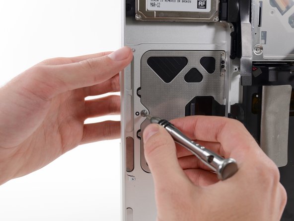
Remove the four silver 1.3 mm Phillips #00 screws from the trackpad spring brackets.
-
-
Este paso está sin traducir. Ayuda a traducirlo
-
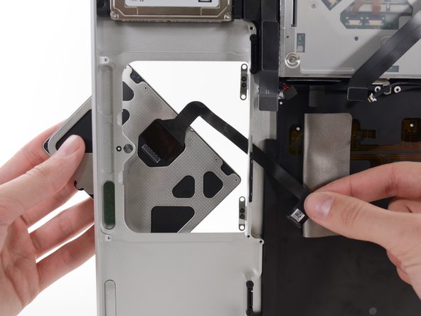
Once the trackpad is free of the upper case, guide the ribbon cable through the slot cut in the upper case.
-
-
Este paso está sin traducir. Ayuda a traducirlo
-
When reinstalling the trackpad, loosely replace the four Phillips screws and check the alignment of the trackpad on the keyboard side of the upper case.
-
Once you have centered the trackpad in the upper case, tighten the Phillips screws all the way.
-
Use the large Tri-point screw at the bottom of the trackpad to adjust the click stroke.
-


Cancelar: No complete esta guía.
70 personas más completaron esta guía.

25 comentarios
Used this guide for a mid-2010 chassis, which seems the same. I'd recommend moving steps 23-25 to happen between steps 3 and 4. Basically, take the battery out first, immediately after removing the bottom cover. Also, replace it as a last step in reassembly prior to placing the bottom cover back on. What I found was that placing the logic board back into the machine (reversing step 22) was difficult with the fairly stiff battery connector cable. If you have better mojo than I do with a spudger, good on ya mate.
Definitely follow the advice about battery out first and the tip regarding double sided tape and corrugated board is really good. Easy to follow steps and worked perfectly.
Do I have to follow all the steps? My battery blew up; shattered the trackpad. Took battery out. Laptop works perfectly but need to replace trackpad. So since the battery is out, do I need to take everything else out, too? I do better with videos than still pictures. Dyslexia rules.
Is it necessary to follow all the steps? My battery blew up; shattered the trackpad. Took battery out. Laptop works perfectly but need to replace trackpad. So since the battery is out, do I need to take everything else out, too? I do better with videos than still pictures. Dyslexia rules.
I have followed the steps, now my keyboard and trackpad is not recognised by mac os............ i have checked the cables, everything is connected......
I'm fed up.