Esta versión puede contener ediciones incorrectas. Cambiar a la última instantánea verificada.
Qué necesitas
-
-
Usa tus dedos para empujar ambas pestañas de liberación de la batería para separarlas de la batería y levanta la batería para sacarla de la computadora.
-
-
-
Retira los tres tornillos Phillips idénticos de la tapa de la memoria.
-
-
-
Retira los dos tornillos Phillips en el compartimiento de la batería cerca del pestillo.
-
-
-
Levanta la parte posterior del estuche y pasa los dedos por los lados, liberando el estuche a medida que avanza. Una vez que hayas liberado los lados, es posible que tengas que mover la caja hacia arriba y hacia abajo para liberar el frente de la caja superior. Esta etapa puede ser bastante complicada.
-
Sobre el lector de DVD hay 4 pestañas retrasadas que se abren verticalmente.
-
Ten en cuenta que las dos pequeñas lengüetas en el frente izquierdo de la caja superior pueden doblarse mientras retiras la caja superior. Al volver a instalarlos, es posible que debas doblarlos hacia atrás para que encajen en las ranuras de la carcasa inferior.
-
-
Este paso está sin traducir. Ayuda a traducirlo
-
Disconnect the two antenna cables attached to the Airport Extreme card.
-
-
Este paso está sin traducir. Ayuda a traducirlo
-
Deroute the Airport antenna cables from their channel in the left speaker.
-
-
-
Este paso está sin traducir. Ayuda a traducirlo
-
Disconnect the iSight, inverter, and left fan cables from the logic board by gently pulling in the direction of each cable.
-
-
Este paso está sin traducir. Ayuda a traducirlo
-
Disconnect the display data cable from the logic board.
-
-
Este paso está sin traducir. Ayuda a traducirlo
-
Remove the silver T6 Torx screw securing the ground loop on the display data cable to the casing.
-
-
Este paso está sin traducir. Ayuda a traducirlo
-
Support the display with one hand while removing the following 3 screws:
-
Two 9.5 mm silver T6 Torx screws with threads on only part of the shaft on the inside of the display hinges.
-
One 9.5 mm silver T6 Torx screw with threads on the entire shaft on the outside of the left hinge.
-
-
Este paso está sin traducir. Ayuda a traducirlo
-
Grasp the display assembly on both sides and lift it up and out of the computer.
-
-
Este paso está sin traducir. Ayuda a traducirlo
-
Remove the two 5 mm Phillips screws from the lower left and right corners of the display (two screws total).
-
-
Este paso está sin traducir. Ayuda a traducirlo
-
Insert the flat end of a spudger perpendicular to the face of the display between the plastic strip attached to the rear bezel and the front bezel.
-
With the spudger still inserted, rotate it away from the display to separate the front and rear bezels.
-
Work along the left edge of the display until the rear bezel is evenly separated from the front bezel.
-
-
Este paso está sin traducir. Ayuda a traducirlo
-
Insert the flat end of a spudger perpendicular to the face of the display between the plastic strip attached to the rear bezel and the front bezel.
-
With the spudger still inserted, rotate it away from the display to separate the front and rear bezels.
-
Work along the right edge of the display until the rear bezel is evenly separated from the front bezel.
-
-
Este paso está sin traducir. Ayuda a traducirlo
-
Insert the flat end of a spudger between the front bezel and the plastic strip attached to the rear bezel near the screw holes at the bottom corners of the display.
-
Rotate your spudger toward the rear bezel to separate it from the front bezel.
-
If necessary, enlarge the gap between the lower edge of the rear bezel and the clutch cover until the two components are completely separated.
-
-
Este paso está sin traducir. Ayuda a traducirlo
-
Lift the rear bezel by its bottom edge and rotate it away from the display assembly to separate the top edge.
-
Remove the rear display bezel from the display assembly.
-
-
Este paso está sin traducir. Ayuda a traducirlo
-
Carefully lift the inverter board out of the clutch cover.
-
-
Este paso está sin traducir. Ayuda a traducirlo
-
Disconnect the LCD backlight from the inverter by pulling its connector away from the inverter board.
-
-
Este paso está sin traducir. Ayuda a traducirlo
-
Disconnect the inverter cable by pulling its connector away from the socket on the inverter.
-
-
Este paso está sin traducir. Ayuda a traducirlo
-
Remove the pieces of yellow kapton tape from the bottom left corner of the display.
-
Peel the three green antenna ground straps off the copper tape along the bottom edge of the LCD.
-
Remove the piece of tape securing the camera cable to the LCD.
-
-
Este paso está sin traducir. Ayuda a traducirlo
-
Remove the pieces of tape covering the display data cable and camera cable connectors.
-
Carefully peel the camera cable off the foam tape along the top edge of the LCD.
-
-
Este paso está sin traducir. Ayuda a traducirlo
-
Gently pull the camera cable away from its socket on the camera board.
-
Pull the display data cable connector away from its socket on the LCD.
-
Pull both cables parallel to the face of the logic board.
-
-
Este paso está sin traducir. Ayuda a traducirlo
-
If you have a Core Duo machine, refer to picture 1 and remove three Phillips screws connecting the clutch assembly to the lower edge of the front display bezel near the display data cable.
-
If you have a Core 2 Duo Model A1211 machine, refer to picture 2 and remove two Phillips screws connecting the clutch assembly to the lower edge of the front display bezel near the display data cable.
-
-
Este paso está sin traducir. Ayuda a traducirlo
-
Remove the small Phillips screw from behind the display data cable.
-
Remove the small rectangular steel bracket by sliding it away from the right clutch hinge.
-
-
Este paso está sin traducir. Ayuda a traducirlo
-
Remove three Phillips screws attaching the clutch assembly to the lower edge of the front display bezel.
-
-
Este paso está sin traducir. Ayuda a traducirlo
-
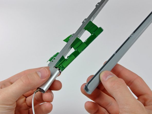
Push the open edge of the clutch cover away from the left clutch hinge to pop it off the clips attaching the two parts.
-
Remove the clutch assembly from the front display bezel.
-
-
Este paso está sin traducir. Ayuda a traducirlo
-
Remove the five small Phillips screw securing the plastic antenna cover to the inside of the clutch cover.
-
-
Este paso está sin traducir. Ayuda a traducirlo
-
Pull the antenna cover off the clutch cover, being careful not to damage the antenna cables.
-


Cancelar: No complete esta guía.
Una persona más ha completado esta guía.
