Esta versión puede contener ediciones incorrectas. Cambie a la última instantánea verificada.
Qué necesitas
-
-
Quitar los siguientes diez tornillos que unen la tapa inferior con el cuerpo:
-
Dos tornillos Pentalobe P5 de 2.3mm
-
Ocho tornillos Pentalobe P5 de 3.0mm
-
-
-
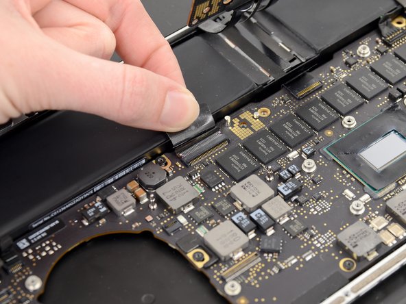
Remueve la cubierta de plástico adherida a la placa de contacto de la batería.
-
-
-
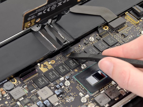
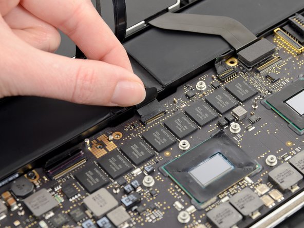
Toma el intercalador con pincita
-
Levanta el intercalador de la placa lógica y remuévelo.
-
-
Este paso está sin traducir. Ayuda a traducirlo
-
Remove the following screws securing the heat sink to the logic board assembly:
-
One 2.4 mm Phillips #00 screw
-
One 3.4 mm T5 Torx screw
-
Four 2.7 mm T5 Torx screws
-
-
Este paso está sin traducir. Ayuda a traducirlo
-
Lift and remove the heat sink up off the logic board assembly.
-
-
Este paso está sin traducir. Ayuda a traducirlo
-
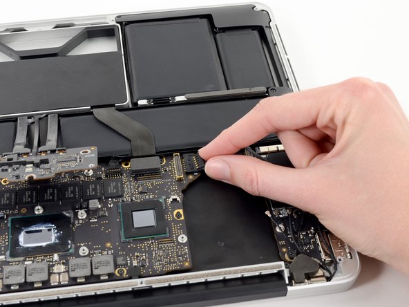
Use the flat end of a spudger to pry the right side of the I/O board data cable connector up off its socket on the I/O board.
-
-
Este paso está sin traducir. Ayuda a traducirlo
-
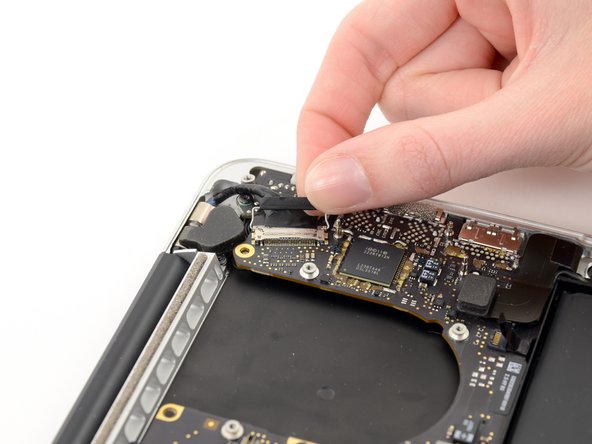
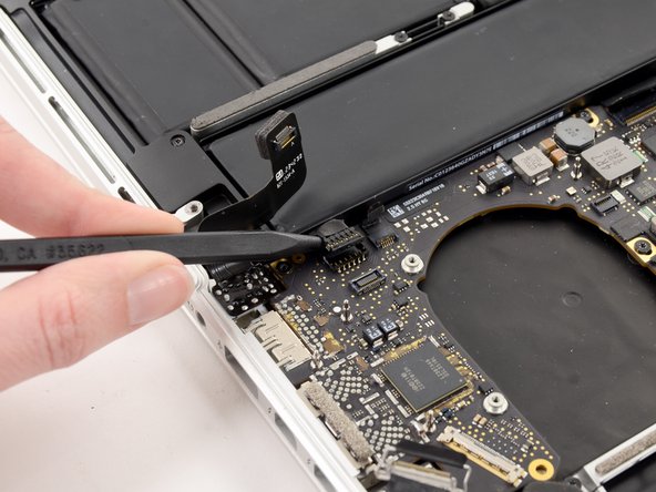
Wedge the flat end of a spudger beneath the left side of the I/O board data cable connector.
-
Gently twist the spudger to disconnect the I/O board data cable connector from its socket on the logic board.
-
-
-
Este paso está sin traducir. Ayuda a traducirlo
-
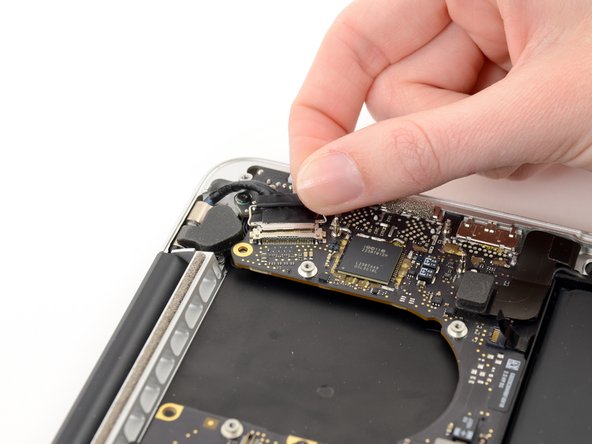
Lift and remove the I/O board data cable from the MacBook Pro.
-
-
Este paso está sin traducir. Ayuda a traducirlo
-
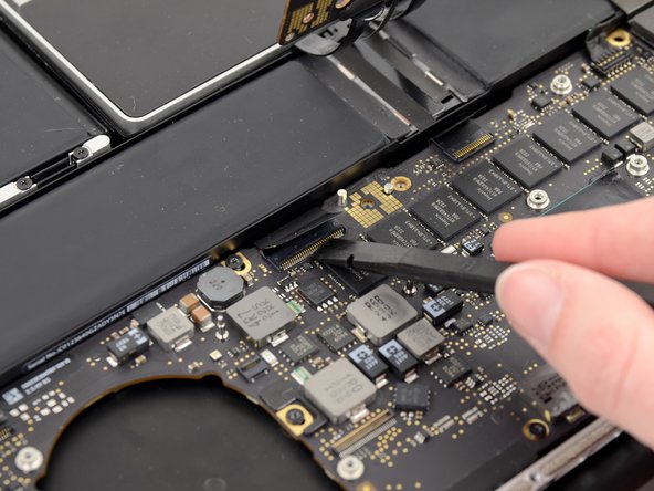
Use the tip of a spudger to push the iSight camera cable connector straight away from its socket on the logic board.
-
-
Este paso está sin traducir. Ayuda a traducirlo
-
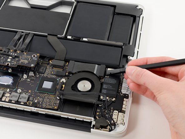
Use the tip of a spudger to flip up the retaining flap on the right fan ribbon cable ZIF socket.
-
Pull the right fan ribbon cable straight out of its socket on the logic board.
-
-
Este paso está sin traducir. Ayuda a traducirlo
-
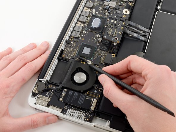
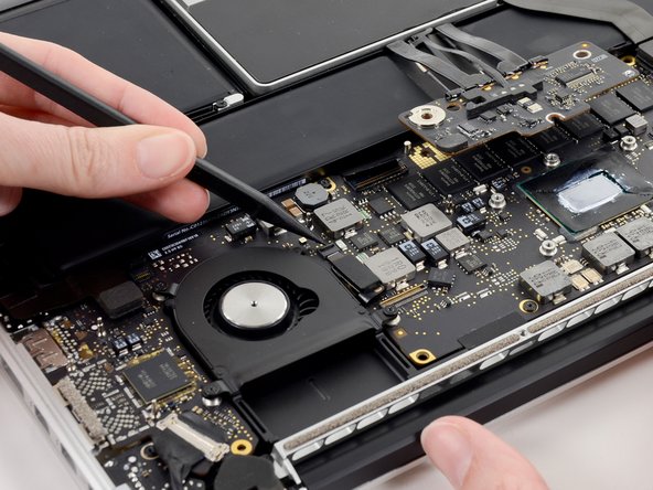
Remove the three 3.1 mm T5 Torx screws securing the right fan to the logic board assembly.
-
-
Este paso está sin traducir. Ayuda a traducirlo
-
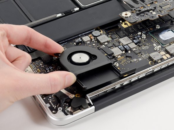
Lift and remove the right fan out of the upper case.
-
-
Este paso está sin traducir. Ayuda a traducirlo
-
Use the tip of a spudger to flip up the retaining flap on the left fan ribbon cable ZIF socket.
-
-
Este paso está sin traducir. Ayuda a traducirlo
-
Remove the three 3.1 mm T5 Torx screws securing the left fan to the logic board assembly.
-
-
Este paso está sin traducir. Ayuda a traducirlo
-
Use the tip of a spudger to push the edges of the I/O board connector straight out of its socket on the logic board.
-
-
Este paso está sin traducir. Ayuda a traducirlo
-
Wedge the flat end of a spudger underneath the keyboard backlight connector and the logic board.
-
Gently twist the flat end of a spudger upwards to pry the keyboard backlight connector up off its socket on the logic board.
-
-
Este paso está sin traducir. Ayuda a traducirlo
-
Grab the black pull tab secured to the display data cable lock and rotate it toward the DC-In side of the computer.
-
Pull the display data cable straight out of its socket on the logic board.
-
-
Este paso está sin traducir. Ayuda a traducirlo
-
Pry the headphone jack cable connector up off its socket on the logic board.
-
-
Este paso está sin traducir. Ayuda a traducirlo
-
Use the tip of a spudger to flip up the retaining flap on the microphone ribbon cable ZIF socket.
-
Grasp the plastic pull tab and pull the microphone ribbon cable out of its socket.
-
-
Este paso está sin traducir. Ayuda a traducirlo
-
Use the flat edge of a spudger to flip up the retaining flap on the keyboard ribbon cable ZIF socket.
-
Grasp the plastic pull tab and pull the keyboard ribbon cable out of its socket.
-
-
Este paso está sin traducir. Ayuda a traducirlo
-
Repeat the previous procedure to disconnect the Trackpad ribbon cable from its socket on the logic board.
-
-
Este paso está sin traducir. Ayuda a traducirlo
-
Wedge the flat end of a spudger beneath the right speaker cable connector.
-
Gently pry the right speaker cable connector up off from its socket on the logic board.
-
-
Este paso está sin traducir. Ayuda a traducirlo
-
Use the flat end of a spudger to pry the SSD cable connector up off its socket on the logic board.
-
-
Este paso está sin traducir. Ayuda a traducirlo
-
Wedge the tip of a spudger beneath the left speaker cable connector.
-
Gently pry the left speaker cable connector up off from its socket on the logic board.
-
-
Este paso está sin traducir. Ayuda a traducirlo
-
Remove the nine 3.3 mm T5 Torx screws securing the logic board and MagSafe DC-in board to the upper case.
-
-
Este paso está sin traducir. Ayuda a traducirlo
-
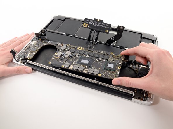
Carefully grasp the corner of the logic board (opposite of the I/O ports) and lift the logic board out of the upper case.
-
-
Este paso está sin traducir. Ayuda a traducirlo
-
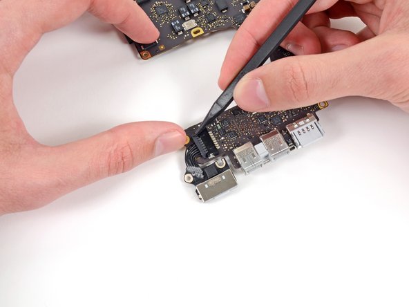
Gently push the edges of the MagSafe cable connector away from its socket on the logic board.
-
-
Este paso está sin traducir. Ayuda a traducirlo
-
Pull the MagSafe cable connector straight out of its socket on the logic board.
-


Cancelar: No complete esta guía.
14 personas más completaron esta guía.

