Saltar al contenido principal

Esta versión puede contener ediciones incorrectas. Cambiar a la última instantánea verificada.

Qué necesitas

  1. , Batería: paso 1, imagen 1 de 1
    • Utiliza una moneda o un spudger para girar el tornillo de bloqueo de la batería 90 grados en el sentido de las agujas del reloj.

  2. : paso 2, imagen 1 de 1
    • Extrae la batería del ordenador.

  3. , Cubierta de la memoria: paso 3, imagen 1 de 1
    • Desatornilla los tres tornillos Phillips espaciados uniformemente a lo largo de la pared posterior del compartimento de la batería.

    • Los tornillos están fijados a la cubierta metálica de la memoria, por lo que no se pueden perder.

    • El uso de la extensión flexible vendida por iFixit te ayudará con este paso.

  4. : paso 4, imagen 1 de 1
    • Sujeta el extremo derecho de la tapa de la memoria en forma de L y, a continuación, tira de ella hacia ti para que salga por la abertura del compartimento de las pilas.

    • Levanta la tapa de la memoria y sácala del ordenador.

  5. , Carcasa Superior,: paso 5, imagen 1 de 1
    • Retira los 3 tornillos siguientes:

    • Un Phillips#00 de 11 mm en el centro de la caja inferior. (Cabeza: 5 mm de diámetro x 0,75 mm de grosor)

    • Dos Phillips #00 de 14,5 mm (cabeza: 5 mm de diámetro x 0,75 mm de grosor)

    • Si los tornillos se clavan en la carcasa, puedes utilizar un destornillador imantado para sacarlos.

    • El más corto de los tres tornillos va en el centro de la carcasa inferior.

  6. : paso 6, imagen 1 de 1
    • Ten mucho cuidado con estos tornillos, ya que pueden desprenderse con facilidad.

    • Podrías utilizar una extensión flexible para minimizar el pelado.

    • Retira los siguientes 3 tornillos de la pared posterior del compartimento de la batería:

    • Un Phillips #0 de 3 mm. (Cabeza: 2,75 mm. dia.)

    • Dos Phillips #0 de 4 mm a cada lado. (Cabeza: 2,75 mm dia.)

  7. : paso 7, imagen 1 de 1
    • Retira los dos tornillos Phillips de cada lado de la pared derecha del compartimento de la batería (no los más cercanos al conector de la batería).

    • Dos Phillips #000 de 6,25 mm. (Cabeza: 4 mm. diá. x 0,5 mm de grosor)

  8. : paso 8, imagen 1 de 1
    • Retira los cuatro tornillos Phillips indicados de la pared frontal del compartimento de la batería. Cuando trabajes desde la izquierda, retira los tornillos 2º, 4º, 7º y 9º.

    • Cuatro Phillips #000 de 3,25 mm. (Cabeza: 4 mm. dia. x 4 mm grosor)

  9. : paso 9, imagen 1 de 1
    • Retira los siguientes 4 tornillos de la parte posterior del ordenador:

    • Dos Phillips #00 de 11 mm, con mango (2,2 mm de diámetro x 2 mm de longitud) (Cabeza: 3,2 mm de diámetro x 0,5 mm de grosor)

    • Dos Phillips #00 de 7,25 mm, con mango (2 mm de diámetro x 3,75 mm de longitud) (cabeza: 3,2 mm de diámetro x 0,5 mm de grosor)

    • Durante el montaje, los dos tornillos más largos van en el interior, y los dos tornillos más cortos van en el exterior.

  10. : paso 10, imagen 1 de 1
    • Retira los dos tornillos Phillips del lado de la unidad óptica (derecha) del ordenador:

    • Dos Phillips #00 de 5,2 mm, con vástago (2,3 mm de diámetro x 3,25 mm de longitud) (Cabeza: 3,2 mm de diámetro x 0,5 mm de grosor)

    • No es necesario quitar los tornillos similares en los puertos (izquierda) lado de la computadora.

  11. : paso 11, imagen 1 de 1
    • Hay un cable plano del teclado y del trackpad que conecta la carcasa superior a la placa lógica, así que no saques la carcasa superior del todo todavía.

    • Utiliza una herramienta de apertura de plástico, un crédito de plástico caducado o una tarjeta de grosor similar para hacer palanca en la carcasa superior, comenzando en la esquina superior izquierda y trabajando alrededor de la parte frontal del ordenador.

    • Es probable que la carcasa superior se atasque en su conexión por encima del borde frontal de la unidad óptica. Si esto ocurre, libera primero todos los demás lados y, a continuación, tira hacia arriba de la carcasa superior desde cualquier lado de la abertura de la unidad óptica.

    • También en este caso puede ser útil introducir una tarjeta de plástico, una púa de guitarra, etc.

    • Si apoyas la base del MacBook sobre un extremo para ver mejor, es posible que desplaces los cuatro clips de plástico gris que sujetan el lado derecho de la carcasa superior. Que no cunda el pánico. Se deslizan en unas ranuras situadas en el borde superior derecho del marco inferior, encima del borde frontal de la unidad óptica.

    • Durante el montaje, asegúrate de que los clips del lado derecho, encima de la unidad óptica, encajan firmemente en su sitio. Son diferentes de los clips del lado izquierdo, por lo que normalmente requieren una presión un poco más firme para encajar en su sitio.

  12. : paso 12, imagen 1 de 3 : paso 12, imagen 2 de 3 : paso 12, imagen 3 de 3
    • Mientras sujetas la carcasa superior, tira hacia arriba de la lengüeta negra del extremo del conector del cable plano plateado para separarlo de la toma del conector en la placa lógica.

    • Si no hay lengüeta negra, también puedes utilizar un spudger para hacer palanca suavemente el conector de su zócalo en la placa lógica. Este conector es alto, así que asegúrate de hacer palanca hacia arriba.

    • Si por casualidad se le rompe el cable de la carcasa superior al desmontarla, tenemos en stock el cable por separado y una guíaque facilita su sustitución.

    • Mientras tienes las mayúsculas quitadas, es un buen momento para quitar el polvo, pelos, etc. Lo mejor es utilizar una lata de aire comprimido, aunque si usas un cepillo, asegúrate de que sus cerdas sean de un material (normalmente pelo de animal) que no genere electricidad estática, que puede destruir los componentes electrónicos.

    • Tras el montaje, hay 4 clips de plástico grises instalados en ranuras a lo largo de la parte superior del marco delante de la unidad óptica (consulta la segunda y tercera imágenes). Estos clips deben estar instalados en sus ranuras para que sus pestañas de acoplamiento en la parte inferior del lado derecho de la carcasa superior encajen en ellos.

  13. , Unidad óptica: paso 13, imagen 1 de 1
    • Sujeta la lengüeta de plástico blanca unida al disco duro y tire de ella hacia la izquierda, extrayendo el disco duro del ordenador.

  14. : paso 14, imagen 1 de 1
    • Retira los dos tornillos Phillips del lateral de la unidad óptica.

    • Dos Phillips #000 de 3,25 mm (cabeza: 4 mm. de diámetro x 0,3 mm de grosor)

  15. : paso 15, imagen 1 de 1
    • Desconecta el conector naranja del cable plano de la unidad óptica de la placa lógica haciendo palanca con el dedo o con un spudger.

  16. : paso 16, imagen 1 de 1
    • Desconecta el enchufe del cable de datos de la pantalla recién descubierto de la placa lógica tirando de él hacia arriba con su lengüeta negra.

    • Si no hay una lengüeta en la parte superior del enchufe, puede ser útil utilizar un spudger para desconectar este enchufe.

  17. : paso 17, imagen 1 de 1
    • Desconecta el enchufe del cable del disco duro recién descubierto de la placa lógica tirando de él hacia arriba con su lengüeta negra.

    • Cuando vuelvas a conectar el enchufe del cable del disco duro a la placa lógica, asegúrate de que el enchufe está colocado debajo de los cables del altavoz derecho y del micrófono, o de lo contrario el enchufe no quedará al ras de la placa lógica, lo que impedirá que el enchufe encaje completamente con su toma en la placa lógica.

  18. : paso 18, imagen 1 de 1
    • Despega la cinta de aluminio situada entre el ventilador y la unidad óptica. Levanta la cinta de aluminio del lado del ventilador, dejándola pegada a la unidad óptica.

    • Durante el montaje, asegúrate de pasar los cables por debajo de la cinta antes de volver a colocarla.

    • Si el adhesivo de esta cinta de aluminio ya no se pega, puedes sujetarla con un trozo de cinta normal, pero no bloquees la entrada del ventilador.

  19. : paso 19, imagen 1 de 1
    • Tira hacia arriba del cable de datos de la pantalla desde el borde de la unidad óptica para revelar un tornillo Phillips plateado.

  20. : paso 20, imagen 1 de 1
    • Retira el tornillo Phillips #00 de 2 mm que sujeta la esquina posterior de la unidad óptica.

    • Cuando vuelvas a instalar este tornillo, asegúrate de que ninguno de los cables cercanos quede atrapado bajo la cabeza del tornillo.

    • Es posible que el cable Bluetooth con cubierta plateada esté tapando el tornillo. Si es así, empújalo con cuidado hacia un lado. Es posible que tengas que quitar el tornillo que sujeta las orejetas de blindaje de tierra para los dos cables cercanos antes de que pueda mover el cable Bluetooth a un lado lo suficiente.

    • Este tornillo es de 7 mm en los modelos anteriores, y puede ser de 4,2 mm en los modelos Santa Rosa/Penryn y 2009.

  21. : paso 21, imagen 1 de 1
    • Levanta la placa de la antena Bluetooth del borde frontal de la unidad óptica.

  22. : paso 22, imagen 1 de 1
    • Desenchufa el cable del disco duro de debajo de los clips situados en el lado cercano de la unidad óptica.

    • Durante el montaje, pasa el cable por debajo de estos clips.

  23. : paso 23, imagen 1 de 1
    • Levanta el lado de la unidad óptica más cercano a usted y, a continuación, desliza la unidad hacia usted, hacia arriba y fuera del ordenador.

    • Sigue estos pasos para reinstalar la unidad óptica:

    • En primer lugar, desliza su lado más cercano a la parte posterior del Macbook por debajo del borde del marco posterior a la izquierda de la bisagra, mientras desliza también la pestaña de montaje de la unidad óptica en su esquina superior izquierda por debajo de los cables en esta ubicación.

    • Baja la unidad parcialmente hasta el alojamiento inferior. Manten el cable del disco duro alejado de la bahía de la unidad óptica.

    • Antes de colocar la unidad por completo en su sitio, utiliza un destornillador para empujar hacia delante (hacia la parte delantera de la unidad) el orificio del tornillo de la lengüeta de montaje de la unidad.

    • Empuja hacia adelante el deslizador, que se extiende a lo largo del lado más alejado de la unidad, para insertar el extremo de este deslizador en un pequeño canal del marco de la carcasa inferior. Esto ayuda a mantener la unidad en su lugar.

    • Cuando empujes el deslizador hacia adelante, si el orificio del tornillo en la lengüeta de montaje de la unidad no se alinea sobre su inserto de latón roscado en la carcasa inferior, el extremo delantero del deslizador no se ha insertado completamente en su canal en el marco.

    • Si el deslizador no se mueve más a la derecha, retire la unidad para ver si el extremo del deslizador está doblado. Si el extremo delantero de la corredera no está doblado, es posible que sea demasiado largo. Utilice un alicate fino para cortar la parte más estrecha del extremo del deslizador. La unidad óptica seguirá firmemente en su sitio.

  24. Este paso está sin traducir. Ayuda a traducirlo

    : paso 24, imagen 1 de 1
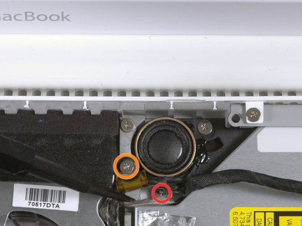
    • For original Macbook Core Duo and Core 2 Duo models, remove these 3 screws:

    • Two 3 mm Phillips near the right speaker.

    • One 6 mm Phillips threaded through a hole in a plastic finger above the subwoofer.

    • When reinstalling the screw above the subwoofer, be careful not to over-tighten it or the subwoofer's plastic could crack.

    • For Santa Rosa/Penryn and 2009 models, which don't have a c-channel:

    • Remove only the single 3 mm Phillips screw from the right speaker, and skip step 26.

  25. Este paso está sin traducir. Ayuda a traducirlo

    : paso 25, imagen 1 de 1
    • Lift the right speaker out of its housing and set it to the side.

  26. Este paso está sin traducir. Ayuda a traducirlo

    : paso 26, imagen 1 de 1
    • If you have a Santa Rosa/Penryn or 2009 model, skip this step.

    • Using a spudger, gently pry up the white plastic slot and slide the metal c-channel to the right and away from the display.

  27. Este paso está sin traducir. Ayuda a traducirlo

    : paso 27, imagen 1 de 1
    • Use a spudger to carefully disconnect the microphone cable from the logic board. You'll want to work from side to side, and slowly wiggle the plug back and out of its socket.

    • Pulling on this plug vertically will break its socket off the logic board. This connector is removed only horizontally by gently pulling the microphone cable toward the screen while working a spudger between the connector and the socket.

  28. Este paso está sin traducir. Ayuda a traducirlo

    : paso 28, imagen 1 de 1
    • Lift up on the black right speaker cable with one hand, and deroute the microphone cable from the silver metal clip just above the right RAM slot.

    • This metal clip may not be present in all models. Be sure that the cable is free from any hold downs around this area before proceeding.

  29. Este paso está sin traducir. Ayuda a traducirlo

    : paso 29, imagen 1 de 1
    • If you didn't remove the ground lug retaining screw in step 20 above, remove it now. It's a 7mm (may be 4mm or 3mm in Santa Rosa/Penryn and 2009 models) Phillips screw securing the ground lugs on the right speaker cable and microphone cable to the metal frame.

  30. Este paso está sin traducir. Ayuda a traducirlo

    : paso 30, imagen 1 de 2 : paso 30, imagen 2 de 2
    • Deroute the microphone cable and the black display data cable from the tabs at the bottom of the subwoofer.

    • During reassembly, while there may seem to be more than one way to route the cables, the best way is as shown in photo 2. Click on the photo for a larger view.

  31. Este paso está sin traducir. Ayuda a traducirlo

    : paso 31, imagen 1 de 1
    • Remove the single 3 mm Phillips screw securing the ground lug in the display data cable located just above the Bluetooth board. This screw may also be securing a ground lug in the speaker cable.

  32. Este paso está sin traducir. Ayuda a traducirlo

    : paso 32, imagen 1 de 2 : paso 32, imagen 2 de 2
    • Disconnect the antenna cables from the Airport card:

    • If you have an original MacBook Core Duo or Core 2 Duo model, see the first picture, which shows that there are three antenna cables.

    • If you have a MacBook Core 2 Duo Santa Rosa/Penryn or 2009 model, there are only two antenna cables, and the plug/socket for the black inverter cable is in a different location. There may be a square foam piece over the plug/socket for the inverter board connector.

    • Disconnect the inverter cable from its socket by inserting a spudger between the right or left ends of the plug and the socket, and prying gently vertically. Do NOT pry up on the socket--you must pull up on the plug alone, vertically out of the socket. Do not pull in the direction of the cable wires or you will tear the socket off the logic board.

  33. Este paso está sin traducir. Ayuda a traducirlo

    : paso 33, imagen 1 de 2 : paso 33, imagen 2 de 2
    • For original Macbook Core Duo and Core 2 Duo models, see first picture and remove the following 2 screws from the right hinge mount:

    • One 6 mm Phillips on the left side of the hinge mount.

    • One 10 mm Phillips on the right side of the hinge mount.

    • For Santa Rosa/Penryn and 2009 models, see second picture and remove the following 3 screws from the right hinge mount:

    • One 3 mm smalller diameter Phillips on the far left.

    • One 5.2 mm larger diameter, 4.2 mm head Phillips in the middle.

    • One 10 mm larger diameter, 4.2mm head Phillips from the far right.

    • Before removing the right hinge mount, take care to see how its pieces fit together, including the small white plastic piece. Knowing how the mount pieces fit together will help with reassembly. Lift the right hinge mount with the small white plastic piece out of the computer.

  34. Este paso está sin traducir. Ayuda a traducirlo

    : paso 34, imagen 1 de 1
    • Hold the display with one hand while removing the following 3 screws from the left hinge mount:

    • One 7.2 mm smaller diameter Phillips from the right side.

    • One 5.2 mm larger diameter Phillips from the middle.

    • One larger diameter 10 mm Phillips from the left side.

    • Before removing the left hinge mount, take care to see how its pieces fit together, including the small white plastic piece. Knowing how the mount pieces fit together will help with reassembly.

    • In 2009 models, the shape of the left hinge mount may be different than shown in the photo, but the locations and sizes of its screws are the same.

    • Lift the left hinge mount with white plastic piece out of the computer.

    • Check that the cables coming out of the right end of the left hinge are not trapped under other cables.

  35. Este paso está sin traducir. Ayuda a traducirlo

    : paso 35, imagen 1 de 1
    • Grasp the display assembly on either side and lift it up and out of the computer, taking care that the cables attached to the display don't snag on parts in the lower case.

  36. Este paso está sin traducir. Ayuda a traducirlo

    : paso 36, imagen 1 de 1
    Herramienta utilizada en este paso:
    Plastic Cards
    $2.99
    Comprar
    • The following steps should be identical for both white and black MacBooks.

    • Use a thin plastic card to release the tabs and their clips holding the front display bezel to the display assembly. There are five tabs along the left side of the display bezel.

    • You may find some display bezels are easier to remove if you work from their inside edges, directly adjacent to/above the LCD panel.

    • Don't use a card that cannot be replaced if damaged. The clips can be difficult to remove and the card can bend and break, rendering it useless.

  37. Este paso está sin traducir. Ayuda a traducirlo

    : paso 37, imagen 1 de 1
    • Continue to free the tabs along the the top edge of the display assembly.

    • Be careful when working near the iSight camera.

  38. Este paso está sin traducir. Ayuda a traducirlo

    : paso 38, imagen 1 de 1
    • Next, free the five tabs securing the display bezel on the right side.

  39. Este paso está sin traducir. Ayuda a traducirlo

    : paso 39, imagen 1 de 2 : paso 39, imagen 2 de 2
    • Lift up the front display bezel from the top and use your plastic card to free the tabs along the bottom edge of the display bezel.

    • Make sure that your card is between the metal frame around the LCD panel and the display bezel and not touching the LCD panel itself.

    • After freeing all holding tabs, lift the front display bezel away from the display assembly.

    • When reinstalling the front display bezel onto the display housing, you may find it easier to get the tabs and clips to connect if you push on the four sides of the bezel in this order: top, bottom, then the sides (left or right). You may have to apply extra pressure along the bottom side of the bezel to get it to snap into place firmly.

  40. Este paso está sin traducir. Ayuda a traducirlo

    : paso 40, imagen 1 de 2 : paso 40, imagen 2 de 2
    • Sometimes when removing the front display bezel, the retaining clips that should remain captive in the LCD brackets come out with the front display bezel. Follow this and the next step to transfer the clips back to the LCD bracket.

    • Use a metal spudger or another thin tool to carefully pry the gray plastic clips off the tabs molded into the front display bezel. A 0.8mm flat screwdriver may be useful for this step. You may find that it's easier to remove some of these clips by prying up on their long sides.

    • Be careful, as the clips are made of thin plastic and are inherently delicate.

  41. Este paso está sin traducir. Ayuda a traducirlo

    : paso 41, imagen 1 de 2 : paso 41, imagen 2 de 2
    • Insert one end of the retaining clip beneath the edge of its recess cut into the LCD bracket.

    • Use the edge of a spudger to push the short hook tab on the underside of the other end of the retaining clip into the recess cut into the LCD bracket.

    • The second picture shows a retaining clip properly installed.

    • You may find it easier to get the short hook tabs on the underside of each end of the clip to fit down inside their cutout in the LCD bracket by first very slightly bending down the two ends of the clip, but be careful not to bend the clips too much--only a slight bend is needed, and too much force will break them.

  42. Este paso está sin traducir. Ayuda a traducirlo

    : paso 42, imagen 1 de 1
    • Remove the three 4.2 mm Phillips screws securing the clutch cover.

  43. Este paso está sin traducir. Ayuda a traducirlo

    : paso 43, imagen 1 de 1
    • While holding the display down with one hand, use your other hand to lift the left end of the clutch cover off the clutch hinge and guide the inverter cable and AirPort cables through the gap in the clutch cover. If the cables snag on the two hooked tabs on the inside end of the clutch cover, free them carefully.

    • It may help to wiggle the clutch cover as you pull it up from the display.

    • During reassembly, make sure not to pinch the black inverter cable or the Airport wires when snapping the left end of the clutch cover back into place. To avoid pinching, it may help to lift up and hold these cables and wires in place at the top of the hinge, rather than leaving them running along the sides of the hinge.

  44. Este paso está sin traducir. Ayuda a traducirlo

    : paso 44, imagen 1 de 2 : paso 44, imagen 2 de 2
    • Lift up the right end of the clutch cover while guiding the display data and iSight cables through the gap and the two hooked tabs at the right end of the clutch cover. If the cables snag on the two hooked tabs, free them carefully.

    • Lift the clutch cover off of the display assembly.

    • During reassembly, avoid pinching the display data and iSight cables. While guiding the right end of the clutch cover into place, but before snapping it down, guide these cables between the two hooked tabs inside the right end of the clutch cover, and up into the curved area of the clutch cover, above the hinge.

    • Also avoid pinching the backlight wires (with the white connector on the end, plugged into the right end of the inverter). They should run under the upper right edge of the clutch cover. In some models, the two wires are gray and black, and in others they're white and pink. They lead into a hole in the lower right edge of the LCD to the backlight.

  45. Este paso está sin traducir. Ayuda a traducirlo

    : paso 45, imagen 1 de 2 : paso 45, imagen 2 de 2
    • Slightly lift the newly-revealed inverter board out of its housing and disconnect the black inverter cable from the left end of the board.

  46. Este paso está sin traducir. Ayuda a traducirlo

    : paso 46, imagen 1 de 2 : paso 46, imagen 2 de 2
    • Disconnect the white inverter cable from the right end of the inverter board.

  47. Este paso está sin traducir. Ayuda a traducirlo

    : paso 47, imagen 1 de 1
    • Remove the inverter board from the display.

Linea de Meta

152 personas más completaron esta guía.

8 comentarios

Awesome site and awesome guide. This exteneded the life of my MacBook. I can't thank you enough!!!!

stuartjwaldner - Contestar

For about 3 years I had been dealing with my screen backlight shuting off. I would then dim the screen up and down until I could get it to stay. Sometimes it would work the first time other times I would be doing it for 10 minutes and other times I would give up for a few hours and come back and the screen would be on again. It would also do this sometimes when I opened the laptop at a certain angle or bumped the computer.

Well after these years very annoying behavior, my screen wont turn back on. I can see my desktop when I shine a light on the screen and hear the fan running so I know the computer works fine.

I've tried unpluging the inverter board to see if it was a loose connection, but that didn't work. I tried wiggling it around until the screen turned on and nothing.... Please help!

Is this a problem with my inverter or the inverter cable? Or the backlight cable?

What parts should I buy?

4321ora - Contestar

Hi, I've had the same trouble. Today I solved with a spray electronic cleaner :)

19fra71 -

Hi everybody! Last year bought a new inverter, new cable and other stuff and replaced. Problem not solved, screen still turning black. Thinking to get a new display, but today bought spray electronic cleaner, sprayed over the display data cable (https://d3nevzfk7ii3be.cloudfront.net/ig...). Problem &&^&^$^ solved! :) Time: 15 mins, money: 5$. Good tutorial tho! :P

19fra71 - Contestar

These are a very comprehensive set of instructions and give a really good grand tour of the innards of a MacBook 8. They are also useful for replacing the hard drive or the optical drive.

Couple of hints:

1. Have on hand some canned compressed air - the inside of a laptop is generally quite full of dust and fluff.

2. Also have on hand some contact cleaner spray (do NOT use degreasers/lubricants/anti rust sprays such as RP 7 or WD 50). Contact cleaner sprays generally only contact isopropyl alchohol. It's good to give exposed contacts a bit of a clean - even grease from fingertips can affect conductivity and hence performance. (If possible, use powder free surgical gloves).

3. Make sure you have the right tools (don't skimp - buy the tools set from iFixit). Not using the right spudger on a plug could be the cause of irreparable damage to the circuit board.

(continued next posting)

brightvt - Contestar

Agregar Comentario

Ver Estadísticas:

Ultimas 24 horas: 4

Ultimos 7 días: 10

Ultimos 30 días: 46

Todo El Tiempo: 110,073