Esta versión puede contener ediciones incorrectas. Cambiar a la última instantánea verificada.
Qué necesitas
-
-
Retira los siguientes 10 tornillos:
-
Dos tornillos Pentalobe de 5 Puntos de 8 mm
-
Ocho tornillos Pentalobe de 5 Puntos de 2.5 mm
-
-
-
Usa el extremo plano de un spudger para hacer palanca en ambos lados cortos del conector de la batería hacia arriba para desconectarlo de su zócalo en la placa lógica.
-
Dobla el cable de la batería ligeramente hacia afuera de la placa lógica para que el conector no entre en contacto accidentalmente con su zócalo.
-
-
-
Retire el único tornillo Torx T5 de 2,9 mm que fija el SSD a la placa lógica.
-
-
Este paso está sin traducir. Ayuda a traducirlo
-
Use the flat end of a spudger to pry the I/O board cable up from its socket on the I/O board.
-
-
Este paso está sin traducir. Ayuda a traducirlo
-
Peel the I/O board cable up from the adhesive securing it to the fan.
-
-
Este paso está sin traducir. Ayuda a traducirlo
-
Use the flat end of a spudger to lift the I/O board connector up and out of its socket on the logic board
-
Remove the I/O board cable.
-
-
Este paso está sin traducir. Ayuda a traducirlo
-
Use the tip of a spudger to carefully flip up the retaining flap on the fan cable ZIF socket.
-
-
Este paso está sin traducir. Ayuda a traducirlo
-
Remove the following three screws securing the fan to the upper case:
-
Two 5.2 mm T5 Torx screws
-
One 3.6 mm T5 Torx screw
-
-
Este paso está sin traducir. Ayuda a traducirlo
-
Lift the fan out of the upper case and carefully pull the fan ribbon cable out of its socket as you remove it from the Air.
-
-
Este paso está sin traducir. Ayuda a traducirlo
-
Remove the following five screws securing the battery to the upper case:
-
Two 5.2 mm T5 Torx screws
-
One 6 mm T5 Torx screw
-
Two 2.6 mm T5 Torx screws
-
-
-
Este paso está sin traducir. Ayuda a traducirlo
-
Lift the battery from its edge nearest the logic board and remove it from the upper case.
-
-
Este paso está sin traducir. Ayuda a traducirlo
-
Use the flat end of a spudger to free the adhesive loop securing the I/O board power cable to the upper case.
-
Disconnect the I/O board by pulling the power cable away from its socket on the logic board.
-
-
Este paso está sin traducir. Ayuda a traducirlo
-
Use the tip of a spudger to flip up the retaining flap on the keyboard backlight ribbon cable ZIF socket.
-
Pull the keyboard backlight ribbon cable out of its socket.
-
-
Este paso está sin traducir. Ayuda a traducirlo
-
Use the tip of a spudger or your fingernail to flip up the retaining flap on the trackpad ribbon cable ZIF socket.
-
Pull the trackpad ribbon cable straight out of its socket toward the front edge of the Air.
-
-
Este paso está sin traducir. Ayuda a traducirlo
-
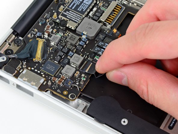
Use the tip of a spudger to de-route the right speaker cable from the slot cut into the logic board.
-
-
Este paso está sin traducir. Ayuda a traducirlo
-
Use the flat end of a spudger to pry the right speaker cable connector up and out of its socket on the logic board.
-
-
Este paso está sin traducir. Ayuda a traducirlo
-
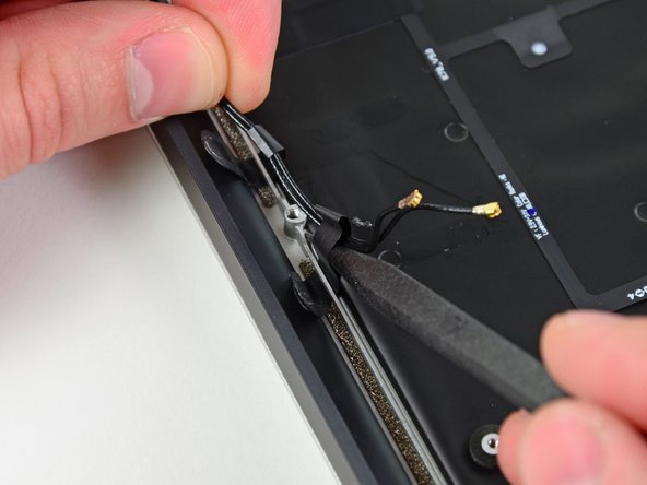
Gently push the tip of a spudger under the black plastic flap stuck to the display data cable lock to make the lock pop upward and away from the socket.
-
Remove the small rubber gasket from the corner of the upper case near the display data cable.
-
-
Este paso está sin traducir. Ayuda a traducirlo
-
While holding the lock away from the socket, gently pull the display data cable out of its socket.
-
-
Este paso está sin traducir. Ayuda a traducirlo
-
Use the flat end of a spudger to pry both antenna cable connectors up and off their sockets on the AirPort/Bluetooth card.
-
-
Este paso está sin traducir. Ayuda a traducirlo
-
Gently de-route the antenna cables from the slot cut into the logic board.
-
-
Este paso está sin traducir. Ayuda a traducirlo
-
Remove the three 3.6 mm T5 Torx screws securing the logic board to the upper case.
-
-
Este paso está sin traducir. Ayuda a traducirlo
-
Gently lift the logic board assembly out of the upper case, minding the fragile heat sink and any cables that may get caught.
-
-
Este paso está sin traducir. Ayuda a traducirlo
-
Remove the small rubber gasket from the corner of the upper case nearest the I/O board.
-
-
Este paso está sin traducir. Ayuda a traducirlo
-
Use the tip of a spudger to carefully flip up the retaining flap on the microphone cable ZIF socket.
-
Pull the microphone ribbon cable straight out of its socket.
-
-
Este paso está sin traducir. Ayuda a traducirlo
-
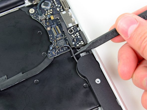
De-route the left speaker cable from the notch cut into the I/O board.
-
Use the flat end of a spudger to pry the left speaker cable connector up and out of its socket on the I/O board.
-
-
Este paso está sin traducir. Ayuda a traducirlo
-
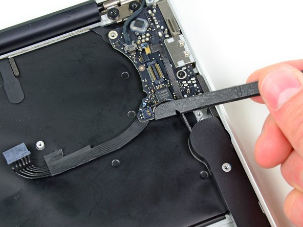
Pull the camera cable parallel to the face of the I/O board toward the rear edge of the Air to disconnect it from its socket.
-
-
Este paso está sin traducir. Ayuda a traducirlo
-
Remove the single 3.6 mm T5 Torx screw securing the I/O board to the upper case.
-
-
Este paso está sin traducir. Ayuda a traducirlo
-
Carefully lift the I/O board from its edge nearest the logic board and remove it from the upper case.
-
-
Este paso está sin traducir. Ayuda a traducirlo
-
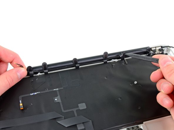
Peel up the six cable loops securing the antenna cables to the upper case.
-
Gently pull the cable loops slightly out of the channel cut into the upper case one at a time.
-
Use your spudger to open up the plastic loops as you de-route the antenna cables through them.
-
Repeat this for all of the retaining loops.
-
-
Este paso está sin traducir. Ayuda a traducirlo
-
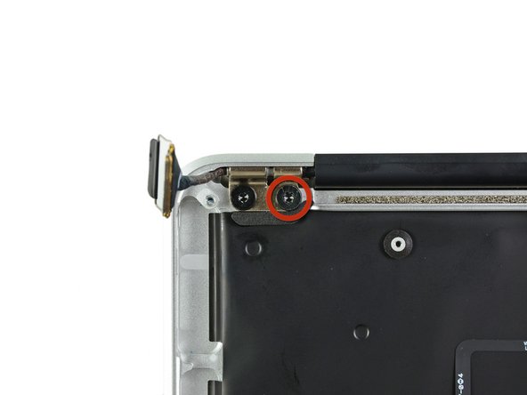
Remove the inner 4.9 mm T8 Torx screw securing each display hinge to the upper case (two screws total).
-
-
Este paso está sin traducir. Ayuda a traducirlo
-
Open the display until it is perpendicular to the upper case and place it on a table as shown.
-
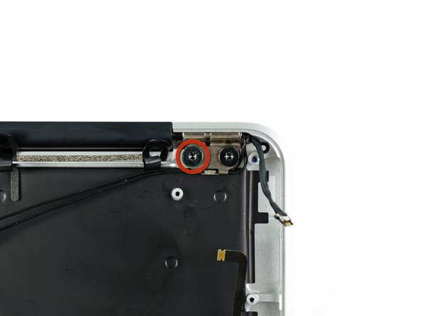
While holding the Air steady, remove the remaining 4.9 mm T8 Torx screw from the lower display bracket.
-
-
Este paso está sin traducir. Ayuda a traducirlo
-
Remove the last 4.9 mm T8 Torx screw securing the display to the upper case.
-
-
Este paso está sin traducir. Ayuda a traducirlo
-
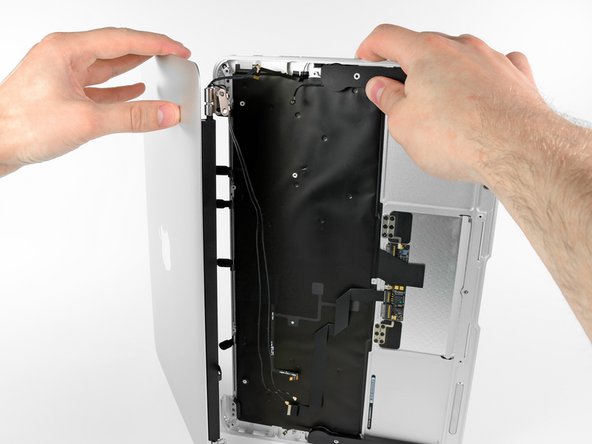
Push the upper case slightly toward the display assembly, then rotate it away from the front of the display assembly.
-
Once the two display hinges have cleared the upper case, remove the display and set it aside.
-


Cancelar: No complete esta guía.
71 personas más completaron esta guía.

5 comentarios
Thanks a lot for this guide! My daughter wrecked the display on my Macbook Air. I have never done any repairs on a notebook before, but I ordered the new display assembly and the toolkit and went ahead anyways.
When I saw my Macbook Air in pieces before me, I had my doubts that it would ever work again, but placing the last screw and then pressing the power button, it just worked!
Thanks again!
Switched two monitors and made a great job thanks to this amzing guide. Very easy.