Saltar al contenido principal

Esta versión puede contener ediciones incorrectas. Cambie a la última instantánea verificada.

Qué necesitas

  1. , Carcasa superior: paso 1, imagen 1 de 2 , Carcasa superior: paso 1, imagen 2 de 2
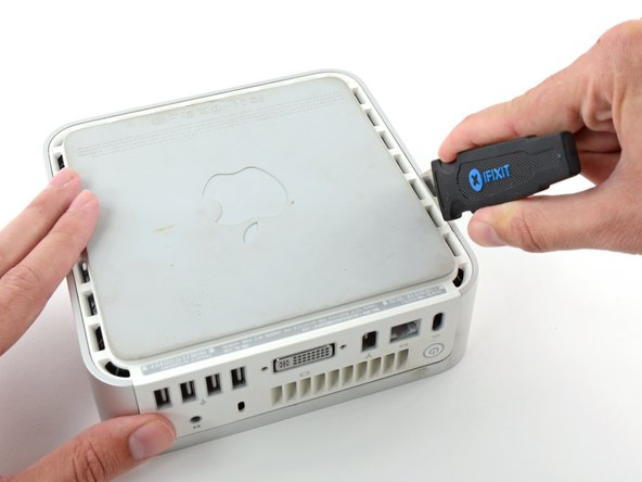
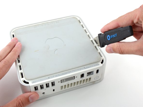
    • Apaga el Mac mini, desconecta todos los cables y dale la vuelta.

    • Inserta el Jimmy en la grieta entre la carcasa superior de aluminio y la carcasa inferior de plástico.

    • Insertar traducción aquí

  2. : paso 2, imagen 1 de 3 : paso 2, imagen 2 de 3 : paso 2, imagen 3 de 3
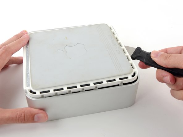
    • Doble suavemente el Jimmy hacia fuera para abrir un poco más la grieta y levante un poco la carcasa inferior.

    • Hay varios clips de plástico en la carcasa inferior que encajan en un canal en la carcasa superior de aluminio. Tu objetivo es utilizar el Jimmy para empujar estos clips hacia adentro lo suficiente como para liberarlos del canal, mientras tiras suavemente hacia arriba de la carcasa inferior.

  3. : paso 3, imagen 1 de 2 : paso 3, imagen 2 de 2
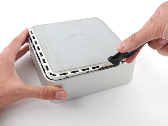
    • Cuando hayas liberado el primer lado, gira el Mac mini y empieza a hacer palanca en el borde frontal.

    • Utiliza el mismo movimiento de palanca para doblar los clips hacia dentro y levantar la carcasa inferior de la carcasa superior.

  4. : paso 4, imagen 1 de 2 : paso 4, imagen 2 de 2
    • Es posible que tengas que mover el Jimmy a lo largo del borde para levantar todos los clips. Ten paciencia y hazlo poco a poco.

  5. : paso 5, imagen 1 de 2 : paso 5, imagen 2 de 2
    • Sigue trabajando alrededor del perímetro, liberando los clips a lo largo del borde final.

  6. : paso 6, imagen 1 de 2 : paso 6, imagen 2 de 2
    • Da la vuelta al Mac mini y levanta la carcasa superior de la inferior.

  7. , Marco interno: paso 7, imagen 1 de 3 , Marco interno: paso 7, imagen 2 de 3 , Marco interno: paso 7, imagen 3 de 3
    • Más adelante en esta guía retirará varios tornillos Phillips empotrados. Los destornilladores de estrella suelen ser demasiado grandes para caber en los huecos, así que asegúrate de tener a mano un destornillador de estrella de eje fino.

    • En primer lugar, retira la antena AirPort (la más grande de las dos), situada cerca del botón de encendido.

    • Aprieta ligeramente los dos brazos de sujeción entre sí y levanta la antena AirPort de su poste.

    • Si aprietas demasiado las dos publicacioneses, seguramente se romperán del marco interno. Trabaja con delicadeza.

    • Durante la reinstalación, tendrás que apretar ligeramente los dos postes para que encajen en las aberturas de la placa de la antena AirPort.

  8. : paso 8, imagen 1 de 2 : paso 8, imagen 2 de 2
    • Utiliza la punta de un spudger para levantar ligeramente el lado izquierdo del bloqueo del cable ZIF de su zócalo.

    • El bloqueo del cable ZIF se levantará aproximadamente 1 mm y se detendrá. No intentes retirar completamente el bloqueo del cable ZIF.

  9. : paso 9, imagen 1 de 1
    • Levanta el cable plano de la tarjeta de audio y sácalo de su alojamiento.

    • Si se niega a levantarse de su zócalo, el bloqueo del cable ZIF no está totalmente liberado. Asegúrese de que se levanta uniformemente aproximadamente 1 mm del zócalo de la placa de interconexión.

  10. : paso 10, imagen 1 de 2 : paso 10, imagen 2 de 2
    • Gira el mini de forma que el mecanismo de carga de la ranura SuperDrive quede orientado hacia usted.

    • Utiliza un par de pinzas para levantar el conector del cable del sensor térmico del disco duro de su zócalo en la placa lógica.

    • Utiliza unas pinzas para agarrar el conector (como se ve en la imagen), no los cables.

    • El conector se encuentra debajo de la abertura de la unidad óptica, junto a la batería PRAM.

  11. : paso 11, imagen 1 de 2 : paso 11, imagen 2 de 2
    • En los siguientes pasos, retirará los cuatro tornillos Phillips que fijan el marco interno a la carcasa inferior. En cada paso se incluye una imagen general que muestra la ubicación general y un primer plano que muestra el tornillo real.

    • Retira el tornillo Phillips empotrado cerca del botón de encendido que fija el marco interno a la carcasa inferior.

  12. : paso 12, imagen 1 de 2 : paso 12, imagen 2 de 2
    • Retira el tornillo Phillips empotrado cerca de la luz de reposo que fija el marco interno a la carcasa inferior.

    • Este tornillo es el más largo de los cuatro tornillos que fijan el marco interno a la caja inferior.

  13. : paso 13, imagen 1 de 2 : paso 13, imagen 2 de 2
    • Retira el tornillo Phillips del marco interno cerca de la antena Bluetooth.

  14. : paso 14, imagen 1 de 2 : paso 14, imagen 2 de 2
    • Retira el tornillo Phillips situado cerca de los puertos de audio que sujeta el marco interno a la carcasa inferior.

  15. : paso 15, imagen 1 de 2 : paso 15, imagen 2 de 2
    • Levanta suavemente el marco interno de la carcasa inferior, teniendo cuidado con la antena AirPort y cualquier otro cable que pueda quedar atrapado.

    • Puede ser necesario tirar hacia arriba cerca de la placa de interconexión para separarla de la placa lógica.

  16. Este paso está sin traducir. Ayuda a traducirlo

    : paso 16, imagen 1 de 1
    • Firmly grasp the power button cable connector with a pair of tweezers and lift it straight up off the logic board.

  17. Este paso está sin traducir. Ayuda a traducirlo

    : paso 17, imagen 1 de 1
    • Firmly grasp the sleep light cable connector with a pair of tweezers and lift it straight up off the logic board.

  18. Este paso está sin traducir. Ayuda a traducirlo

    : paso 18, imagen 1 de 1
    • Remove the single T10 torx lug securing the logic board to the bottom housing.

  19. Este paso está sin traducir. Ayuda a traducirlo

    : paso 19, imagen 1 de 1
    • Use the flat end of a spudger to slightly lift the logic board near the PRAM battery to separate it from the bottom housing.

    • It will be necessary to gently pull the sleep light (shown in red) away from the mini to clear the edge of the logic board.

  20. Este paso está sin traducir. Ayuda a traducirlo

    : paso 20, imagen 1 de 1
    • Gently lift the free end of the logic board and wiggle the board as you pull it away from the I/O ports.

  21. Este paso está sin traducir. Ayuda a traducirlo

    : paso 21, imagen 1 de 2 : paso 21, imagen 2 de 2
    • Before removing the processor you must first remove the aluminum heat sink.

    • To avoid bending the fins, don't squeeze the upper portion of the heat sink perpendicular to the length of the fins.

    • A spring loaded plastic pin at each corner of the heat sink holds it firmly against the face of the processor.

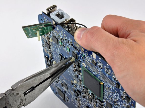
    • The pins have barbs at one end that expand once the pin passes through the logic board. The barbs must be squeezed together to fit through the holes in the logic board. Use extreme caution when squeezing the barbs together with pliers near the exposed face of the logic board.

  22. Este paso está sin traducir. Ayuda a traducirlo

    : paso 22, imagen 1 de 2 : paso 22, imagen 2 de 2
    • This step requires working with both hands and may be better accomplished with the logic board sitting in your lap.

    • Using a plastic opening tool (or similar) in one hand, push down one pin holding the heat sink on the logic board. The spring under the pin will provide moderate resistance.

    • While holding the pin down from the heat sink side of the board, use a pair of pliers in your other hand on the underside of the board to squeeze both barbs against the plastic shaft of the pin.

    • With both barbs squeezed together, push the pin through its hole in the logic board.

    • Repeat this process for each of the four pins holding the heat sink on the logic board.

  23. Este paso está sin traducir. Ayuda a traducirlo

    : paso 23, imagen 1 de 1
    • The heat sink is still attached to the logic board by the thermal sensor cables.

    • Lift the heat sink off the processor and lay it on the AirPort card.

  24. Este paso está sin traducir. Ayuda a traducirlo

    : paso 24, imagen 1 de 3 : paso 24, imagen 2 de 3 : paso 24, imagen 3 de 3
    • Use the tip of a spudger to push the heat sink thermal sensor connector out of its socket.

    • It may be necessary to work from alternating sides to 'walk' the connector out of its socket.

    • Remove the heat sink and set it aside.

  25. Este paso está sin traducir. Ayuda a traducirlo

    : paso 25, imagen 1 de 2 : paso 25, imagen 2 de 2
    • To unlock the processor, use a small flathead screwdriver to rotate the processor lock 180 degrees counter-clockwise until the indicator is near the open lock symbol.

  26. Este paso está sin traducir. Ayuda a traducirlo

    : paso 26, imagen 1 de 1
    • Grab the processor by its edges and lift it straight up off its socket.

    • Rotating the processor while lifting it out has the potential to break pins off inside the socket. Lift it straight up.

  27. Este paso está sin traducir. Ayuda a traducirlo

    : paso 27, imagen 1 de 3 : paso 27, imagen 2 de 3 : paso 27, imagen 3 de 3
    • Processors are extremely sensitive to electrostatic discharge. Only handle your processor by its edges.

    • To aid in installation, processors and sockets have a small alignment arrow (shown in red) so the chip is installed in the correct orientation.

    • Align the chip so that the arrow in its upper right corner corresponds to the arrow molded into the upper right corner of the socket.

    • Carefully lower the processor onto its socket.

    • Note that if you are upgrading from a core solo or core duo processor to a core 2 duo processor and wish to run operating systems of Lion or later, you must delete the hidden file /System/Library/CoreServices/PlatformSupport.plist after the upgrade.

  28. Este paso está sin traducir. Ayuda a traducirlo

    : paso 28, imagen 1 de 1
    • Use a small flathead screwdriver to rotate the processor lock 180 degrees clockwise until the indicator points toward the closed lock symbol.

  29. Este paso está sin traducir. Ayuda a traducirlo

    : paso 29, imagen 1 de 2 : paso 29, imagen 2 de 2
    • Now that the processor is in place, turn your attention to the heat sink.

    • Apple uses a thermally conductive film that must be removed prior to reinstalling the heat sink.

    • Use a razor blade (or anyother flat object such as a credit card, etc.) to remove all of the old solidified thermal material from the heat sink.

    • Next use a small amount of rubbing alcohol to remove all traces of the old thermal material.

    • Allow the heat sink to dry before proceeding.

  30. Este paso está sin traducir. Ayuda a traducirlo

    : paso 30, imagen 1 de 1
    • Apply a thin layer of thermal paste to the reflective silicon face of the processor.

    • Check out our thermal paste guide for detailed instructions on applying thermal paste.

  31. Este paso está sin traducir. Ayuda a traducirlo

    : paso 31, imagen 1 de 1
    • Lay the heat sink on the AirPort card and use a spudger to reconnect the heat sink thermal sensor.

  32. Este paso está sin traducir. Ayuda a traducirlo

    : paso 32, imagen 1 de 1
    • Position the heat sink the same way it will permanently sit before lowering it onto the processor to avoid spreading thermal paste on regions not in contact with the processor.

    • Gently lower the heat sink onto the processor.

  33. Este paso está sin traducir. Ayuda a traducirlo

    : paso 33, imagen 1 de 2 : paso 33, imagen 2 de 2
    • While holding the heat sink in place, press the four plastic posts down through the logic board to reattach the heat sink.

Linea de Meta

169 personas más completaron esta guía.

43 comentarios

I'm learning from cpu-world.com that the Core Duo (and Core Solo) are 32-bit architecture, whereas the Core 2 Duo is a 64-bit design. Does this matter in any way?

Richard - Contestar

Hi Richard. I realize this post is very old, but did you ever get an answer to your question as to whether the 64-bits of the Core 2 Duo Processor will be recognized/utilized in the 32-bit architecture of the Mac Mini A1176? Thanks, John

John Trevett -

Hi. I'm afraid I can no longer answer the question "does it matter in any way", since I eventually upgraded to a new Mac Mini.

I can say that it didn't *seem* to matter, which means no software failed to run or performed noticeably poorly because of the upgrade. But I'm not especially performance sensitive, so it is possible that all/most/some software was running in 32-bit mode and not taking advantage of the higher throughput of a 64-bit architecture. The most CPU intense stuff I was running when I decided to upgrade was: Parallels running WinXP and some Windows-only legal software, along with Chrome with far too many tabs open, and iTunes. That proved to be too much, and it'd slow to a crawl too often. But I think the upgrade kept me on that iMac and extra two or three years, and was an interesting exercise.

Richard -

Hi, the processor will work just fine, but it’s recommended to do an EFI upgrade from 1,1 to 2,1, then you can run Lion and unofficially newer OSes

Arek Plewa -

When going to all the trouble of replacing the CPU, a few other upgrades can be done at the same time:

- Upgrade RAM to 2GB maximum (required for OS X Lion), for example, Crucial CT541128

- Upgrade internal 2.5" SATA hard drive to larger size, and/or faster 7400 RPM or SDD.

- Replace PRAM battery with a fresh one (CR2032 lithium 3V)
Jake Errs - Contestar

Agregar Comentario

Ver Estadísticas:

Ultimas 24 horas: 10

Ultimos 7 días: 39

Ultimos 30 días: 250

Todo El Tiempo: 224,605