Esta versión puede contener ediciones incorrectas. Cambie a la última instantánea verificada.
Qué necesitas
-
Este paso está sin traducir. Ayuda a traducirlo
-
Slide the orange latch sideways to eject the battery.
-
Remove the battery from the battery slot.
-
-
Este paso está sin traducir. Ayuda a traducirlo
-
Using a Phillips #00 screwdriver, remove two 5.39 mm screws next to the battery slot.
-
Remove the metal piece holding down the lanyard, then remove the lanyard.
-
-
Este paso está sin traducir. Ayuda a traducirlo
-
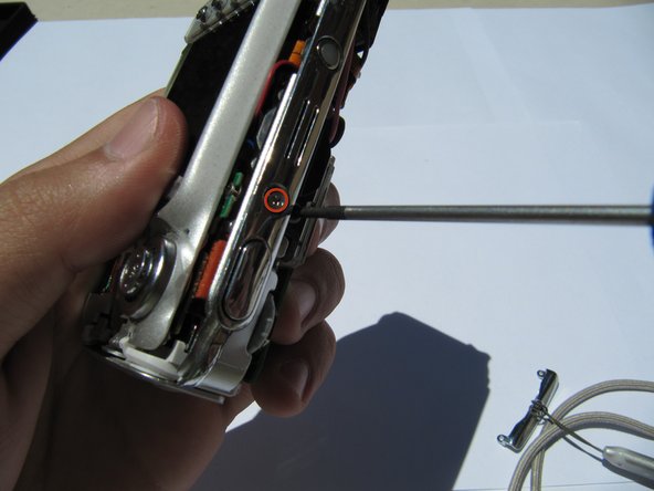
Using a Phillips #00 screwdriver, remove seven screws located on the outside case of the camera.
-
One 6.25 mm screw is located on the top right corner, right to the "OK" button.
-
Four 4.45 mm screws are on the bottom of the camera.
-
Two 2.95 mm screws are on the left side of the camera, above the USB port.
-
-
Este paso está sin traducir. Ayuda a traducirlo
-
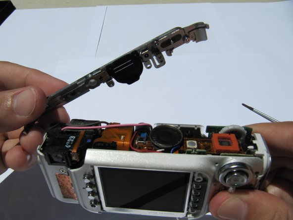
Carefully remove the rear camera casing.
-
Carefully remove the front camera casing.
-
-
-
Este paso está sin traducir. Ayuda a traducirlo
-
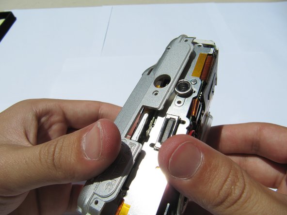
Remove the back panel screws (1x 3.33mm, and 1x 3.40mm).
-
-
Este paso está sin traducir. Ayuda a traducirlo
-
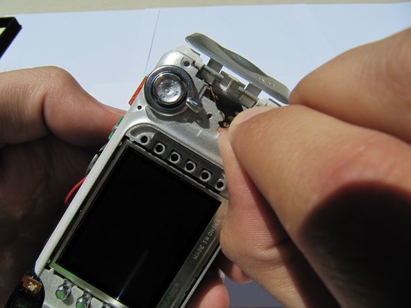
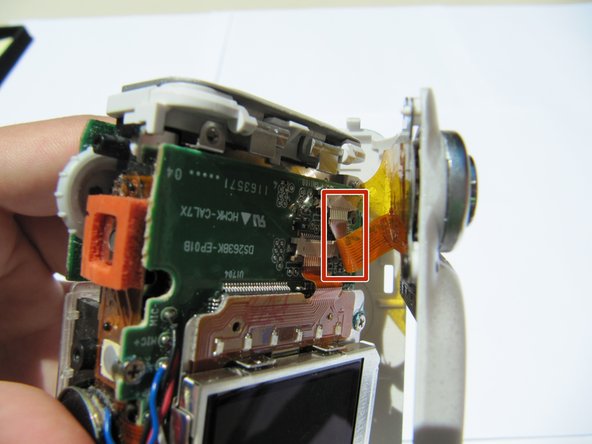
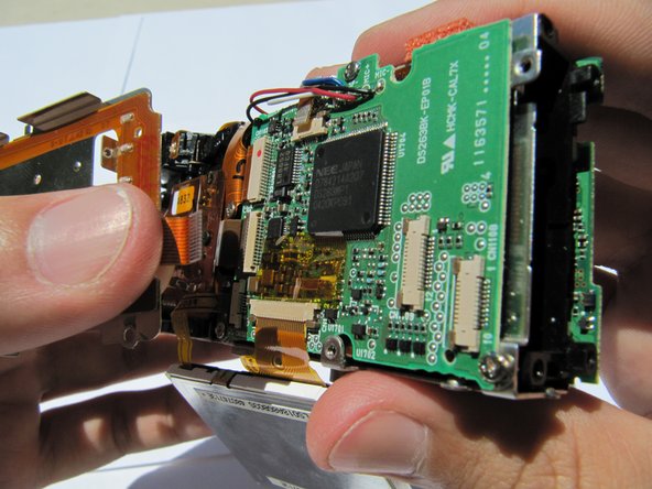
Gently pull the orange tab out of the circuit board.
-
-
Este paso está sin traducir. Ayuda a traducirlo
-
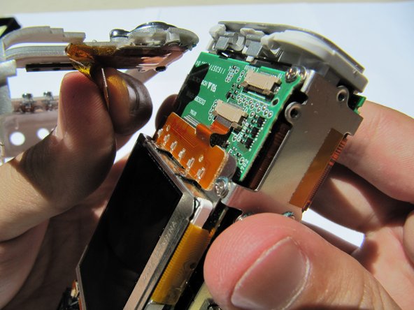
Remove the (1x 3.33mm) screw from the menu button panel .
-
-
Este paso está sin traducir. Ayuda a traducirlo
-
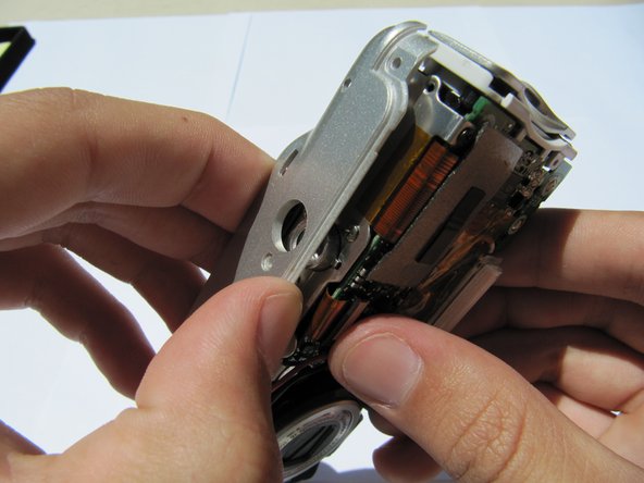
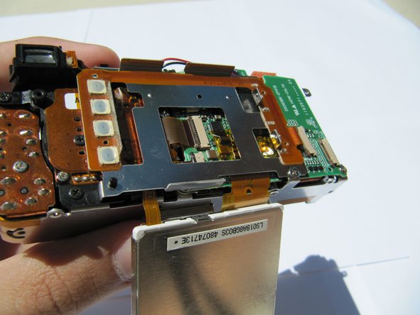
Pull the second orange tab from the circuit board and remove the buttons.
-


Cancelar: No complete esta guía.
Una persona más ha completado esta guía.
Equipo

Cal Poly, Team 2-8, Johann Summer 2010 Miembro de Cal Poly, Team 2-8, Johann Summer 2010
CPSU-JOHANN-R10S2G8
5 Miembros
16 Guías creadas