Esta versión puede contener ediciones incorrectas. Cambiar a la última instantánea verificada.
Qué necesitas
-
Este paso está sin traducir. Ayuda a traducirlo
-
Remove the rubber rings from either end of the device.
-
If there is difficulty in lifting the rings from the device, use the metal spudger.
-
-
Este paso está sin traducir. Ayuda a traducirlo
-
Remove the four 4.8mm Phillips #1 screws from each end of the device with the Phillips head screwdriver.
-
Lift the end pieces off of the device.
-
-
Este paso está sin traducir. Ayuda a traducirlo
-
Remove the four 9.5mm Phillips #1 screws from each end of the device.
-
-
Este paso está sin traducir. Ayuda a traducirlo
-
Peel one end off and slowly draw it across the length of the device until you get to the other side.
-
-
Este paso está sin traducir. Ayuda a traducirlo
-
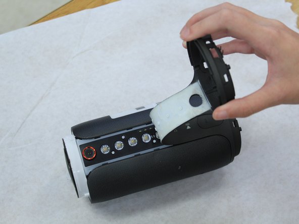
Remove the four 7.9mm Phillips #1 screws along the black centerpiece of the device between the camera and the auxiliary port.
-
Lift up the casing and circuit board but do not try and remove the ribbon wires.
-
-
Este paso está sin traducir. Ayuda a traducirlo
-
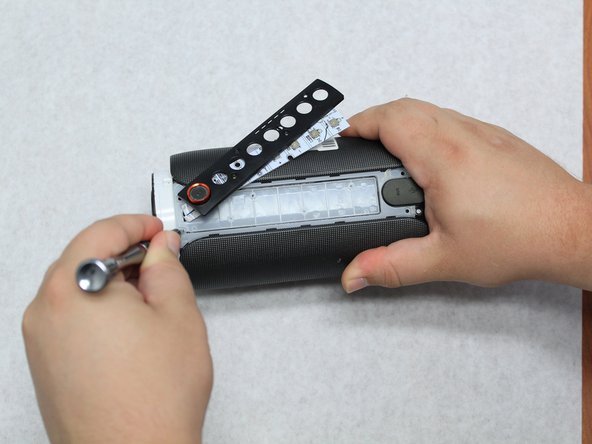
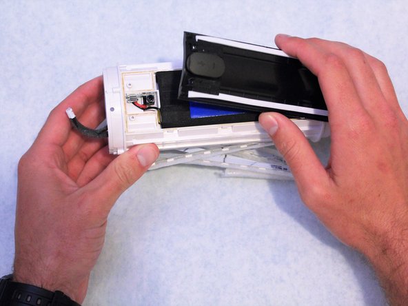
Remove the cover from the end that the ribbon wires are attached to. It should peel off easily.
-
-
Este paso está sin traducir. Ayuda a traducirlo
-
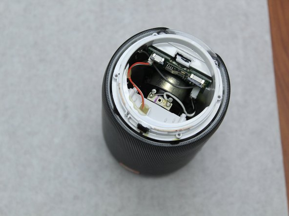
Unlatch the mechanism holding the ribbon wires in place, then disconnect them from the motherboard.
-
To access the wires, remove some of the black glue holding them in place with the spudger.
-
-
-
Este paso está sin traducir. Ayuda a traducirlo
-
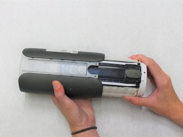
Remove the four 7.9mm Phillips #1 screws around the edges of the center piece.
-
Slide the outer casing off away from the auxiliary and micro USB port.
-
-
Este paso está sin traducir. Ayuda a traducirlo
-
Remove the other end of the device to access the wiring underneath it.
-
-
Este paso está sin traducir. Ayuda a traducirlo
-
Use the angled tweezers to disconnect the battery from the motherboard. It will take some work to remove this piece.
-
-
Este paso está sin traducir. Ayuda a traducirlo
-
Remove the four 7.9mm Phillips #1 screws from the black centerpiece of the device.
-
-
Este paso está sin traducir. Ayuda a traducirlo
-
Use the spudger to reach under the sides of the black centerpiece to access the six latches, three of which are on each side.
-
-
Este paso está sin traducir. Ayuda a traducirlo
-
Lift the black centerpiece off with the metal spudger to reveal the battery underneath.
-
-
Este paso está sin traducir. Ayuda a traducirlo
-
Use a hot air gun to soften the hot glue in order to fully remove the battery.
-
-
Este paso está sin traducir. Ayuda a traducirlo
-
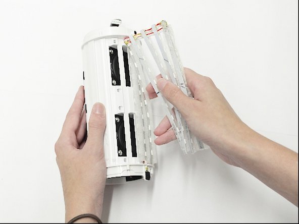
Remove the LED strips from the outside of the white plastic casing.
-
-
Este paso está sin traducir. Ayuda a traducirlo
-
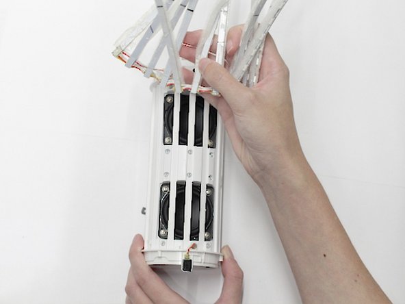
Use the Phillips #1 screwdriver to remove the ten 9.5mm screws that hold the cage in place.
-
Lift the cage off to access the internal components.
-
-
Este paso está sin traducir. Ayuda a traducirlo
-
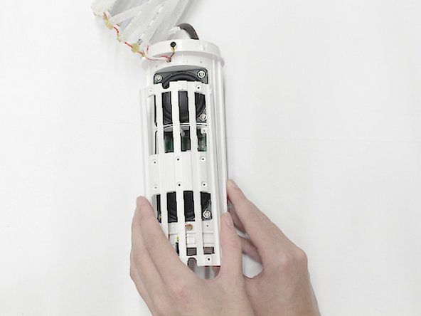
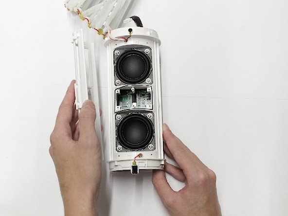
Use the Phillips #1 screwdriver to remove the eight 6.4mm screws that hold the speakers in place.
-
Partially remove the speakers so that you can access the components underneath them.
-
-
Este paso está sin traducir. Ayuda a traducirlo
-
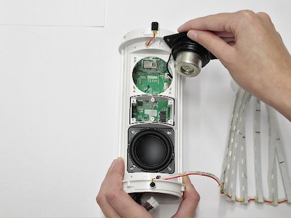
Use the straight tweezers to disconnect the speakers from the motherboard.
-
Fully remove the speakers once they are disconnected from the motherboard.
-


Cancelar: No complete esta guía.
2 personas más completaron esta guía.
Equipo

Western Carolina University, Team S1-G1, Virtue Fall 2018 Miembro de Western Carolina University, Team S1-G1, Virtue Fall 2018
WCU-VIRTUE-F18S1G1
4 Miembros
9 Guías creadas