Esta versión puede contener ediciones incorrectas. Cambie a la última instantánea verificada.
Qué necesitas
-
-
Remueve los dos tornillos Pentalobe P2 de 3.6 mm localizados en las esquinas del conector dock.
-
El Destornillador de 5-Puntas solo debe ser utilizado una vez porque tiene la posibilidad de barrer el tornillo.
-
-
-
Remueve los siguientes tornillos asegurando el conector de la batería a la tarjeta lógica
-
Un tornillo Phillips de 1.7 mm
-
Un tornillo Phillips de 1.5 mm
-
-
-
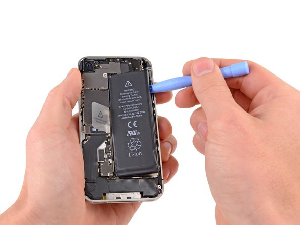
Inserta el borde de una herramienta de apertura de plástico entre la batería y la carcasa exterior cerca del borde inferior del iPhone.
-
Corre la herramienta de apertura de plástico junto el borde derecho de la batería y has palanca en varios puntos para separar completamente del adhesivo asegurándola a la carcasa exterior.
-
Espera por alrededor de un minuto para que el alcohol debilite el adhesivo.
-
Usa el lado plano de una herramienta de apertura de plástico para levantar gentilmente la batería.
-
-
-
Retira los siguientes tornillos sosteniendo la cubierta del cable del conector dock a la placa lógica
-
Un tornillo Phillips de 1.5 mm
-
Un tornillo Phillips de 1.2 mm
-
Retira la cubierta metálica del cable del conector dock
-
-
-
Este paso está sin traducir. Ayuda a traducirlo
-
Use a SIM eject tool or a paperclip to eject the SIM and its tray.
-
Remove the SIM and its tray.
-
-
Este paso está sin traducir. Ayuda a traducirlo
-
Remove the five cables near the top of the logic board in the following order:
-
Headphone jack/volume button cable
-
Front facing camera cable
-
Digitizer cable
-
Display data cable
-
Power button cable (located underneath the headphone jack/volume button cable as shown in the second picture.)
-
-
Este paso está sin traducir. Ayuda a traducirlo
-
Remove the 1.5 mm Phillips screw securing the grounding clip to the logic board near the headphone jack.
-
-
Este paso está sin traducir. Ayuda a traducirlo
-
Use the tip of a spudger to pry the small grounding clip up off the logic board.
-
Carefully grasp the grounding clip and remove it from the iPhone.
-
-
Este paso está sin traducir. Ayuda a traducirlo
-
Remove the 4.8 mm standoff screw near the headphone jack.
-
-
Este paso está sin traducir. Ayuda a traducirlo
-
Use the edge of a plastic opening tool to disconnect the Wi-Fi antenna from the logic board.
-
-
Este paso está sin traducir. Ayuda a traducirlo
-
If present, peel the piece of black tape covering the hidden screw near the power button.
-
Remove the 2.6 mm Phillips screw securing the logic board near the power button.
-
-
Este paso está sin traducir. Ayuda a traducirlo
-
Remove the following screws securing the logic board to the case:
-
One 2.5 mm Phillips screw near the vibrator motor
-
One 2.4 mm Phillips screw
-
One 3.6 mm standoff along the side of the logic board nearest the battery opening.
-
-
Este paso está sin traducir. Ayuda a traducirlo
-
Carefully lift the logic board from the end closest to the speaker enclosure and slide it away from the top edge of the iPhone.
-
Remove the logic board.
-
-
Este paso está sin traducir. Ayuda a traducirlo
-
Remove the adhesive protection on the Wi-Fi/bluetooth chip.
-
Now we can see the Murata SS1830010 chip.
-
-
Este paso está sin traducir. Ayuda a traducirlo
-
Put the logic board in a PCB holder or small vise, to safely hold it while reflowing (it's going to get hot!).
-
Protect the logic board with Kapton tape that has good insulating and temperature characteristics (temperature range: −269 to +400 °C).
-
-
Este paso está sin traducir. Ayuda a traducirlo
-
Now we need a hot air rework station with a small nozzle:
-
-
Este paso está sin traducir. Ayuda a traducirlo
-
Edit: the correct temperature is almost 180-200 °C because around the chip there is a little black protection that can go under the chip.
-
Set a low air flow: 1 or 2 (on a 1 to 7 scale).
-
Now, doing circular movement, you have to reflow for 4-5 minutes.
-
After 5 minutes, gradually decrease the temperature from 200 to 0 °C.
-
-
Este paso está sin traducir. Ayuda a traducirlo
-
After reflowing, wait ten minutes to allow the logic board to cool before handling it.
-
-
Este paso está sin traducir. Ayuda a traducirlo
-
These are the pictures before and after the reflow:
-
In the first image, the Wi-Fi color is light grey (not working).
-
In the second image, the Wi-Fi color is dark grey (working).
-


Cancelar: No complete esta guía.
188 personas más completaron esta guía.
124 comentarios
Mille grazie, Andrea! I completed the repair thanks to your awesome Guide. Could it be you forgot to describe disassembly of the camera + surroundings? I took it out, too.
However, thank you,
Alex
Feel free to describe...
floresc -
you dont need to take out the surrounding and the vibrator, you have just to take out the motherboard, so u dont need to do that..
the camera yes, you have to pull out. im sorry
reply to @Alex Holzhey
Thank you! i'm happy to hear this. and i'm glad to know that my guide is useful. anyway i have done a "copy and paste" for the first 20 steps, so i dont care about if something is the guide is missing..i think that if someone wanna try this guide, he have to know a little how to disassemble his phone. :)
Thanks again