Esta versión puede contener ediciones incorrectas. Cambie a la última instantánea verificada.
Qué necesitas
-
Este paso está sin traducir. Ayuda a traducirlo
-
Using the PH#00 screwdriver, remove the two 0.145 inch Phillips head screws.
-
-
Este paso está sin traducir. Ayuda a traducirlo
-
Insert the plastic opening tool between the screen cover and rear cover of the tablet.
-
Grasp the small suction cup.
-
-
-
Este paso está sin traducir. Ayuda a traducirlo
-
Slide the plastic opening tool along device edge to separate the screen cover from the rear cover.
-
Pull upward on the small suction cup handle while sliding the opening tool.
-
-
Este paso está sin traducir. Ayuda a traducirlo
-
Use the plastic opening tool to remove the speaker from the rear cover.
-
-
Este paso está sin traducir. Ayuda a traducirlo
-
Once the speaker is disconnected, the cover removal is complete.
-
-
Este paso está sin traducir. Ayuda a traducirlo
-
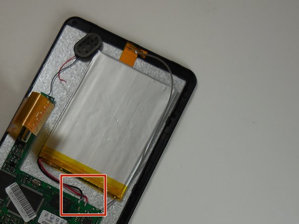
Remove the black placement tape from the battery.
-
Find the two battery solder connections on the circuit board.
-
-
Este paso está sin traducir. Ayuda a traducirlo
-
Remove the red and black battery wires from the circuit board with the solder removal tool.
-
-
Este paso está sin traducir. Ayuda a traducirlo
-
Solder the new battery wire connectors to the circuit board.
-


Cancelar: No complete esta guía.
Una persona más ha completado esta guía.
Equipo

Colorado Springs, Team 5-6, Panko Spring 2015 Miembro de Colorado Springs, Team 5-6, Panko Spring 2015
UCCS-PANKO-S15S5G6
3 Miembros
10 Guías creadas