Esta versión puede contener ediciones incorrectas. Cambiar a la última instantánea verificada.
Qué necesitas
-
-
Coloca un dedo en el borde superior del conjunto de la cubierta del compartimento y desliza el conjunto hacia la parte delantera del Vive hasta que se suelte del auricular.
-
Levanta la tapa para separarla del auricular y deslízala hacia arriba por los cables hasta que quede fuera del camino.
-
-
-
Levanta el cable HDMI hacia arriba para desenchufarlo del auricular.
-
-
-
Repite el proceso de levantar y desenchufar con el resto de los cables USB, de alimentación y de audio.
-
-
Este paso está sin traducir. Ayuda a traducirlo
-
Use a T5 Torx driver to remove the two 12 mm-long screws securing the head strap mounts on either side of the headset.
-
-
Este paso está sin traducir. Ayuda a traducirlo
-
Slide the facerest straight away from the headset to remove it.
-
-
Este paso está sin traducir. Ayuda a traducirlo
-
Use tweezers to remove the small stickers over the four screws securing the outer shell.
-
Use a T5 Torx driver to remove the four 3.4 mm-long screws securing the outer shell.
-
-
Este paso está sin traducir. Ayuda a traducirlo
-
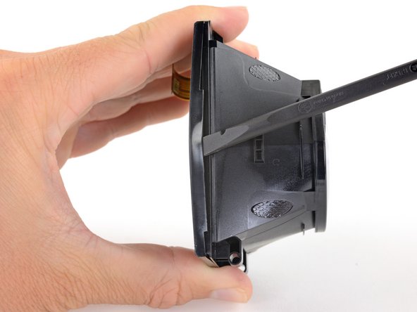
Grasp the top edge of the right half of the outer shell, behind the component cover and near the seam in the center. Pull it to the right and upward, away from the headset to release the clip securing that part of the shell.
-
-
Este paso está sin traducir. Ayuda a traducirlo
-
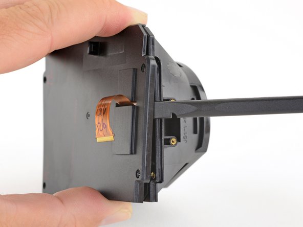
Grasp the right half the outer shell and pull it to the right and toward the front of the headset in a twisting motion until you feel the clips on the front of the cover release.
-
-
Este paso está sin traducir. Ayuda a traducirlo
-
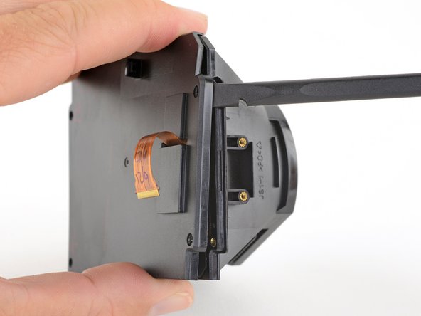
Slide the right side of the outer shell to the right and off of the headset.
-
-
Este paso está sin traducir. Ayuda a traducirlo
-
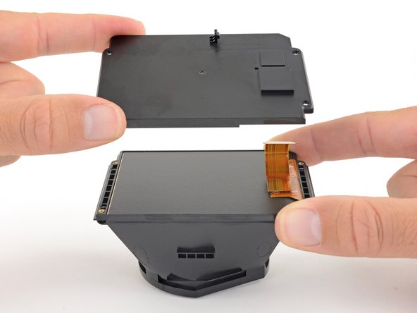
Repeat the last three steps for the left side of the outer shell and remove it.
-
-
Este paso está sin traducir. Ayuda a traducirlo
-
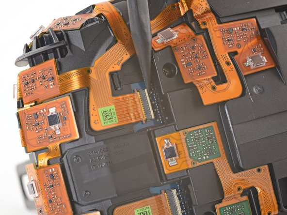
Use tweezers to remove the clear tape over all four of the sensor array cable connectors.
-
-
Este paso está sin traducir. Ayuda a traducirlo
-
Use the pointed end of a spudger to flip up the small locking flap on one of the sensor array ZIF connectors.
-
Slide the cable straight out of its socket on the motherboard.
-
-
Este paso está sin traducir. Ayuda a traducirlo
-
Repeat the previous step for the remaining three sensor array cables to disconnect the remaining cables.
-
-
Este paso está sin traducir. Ayuda a traducirlo
-
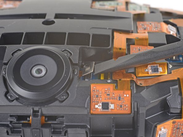
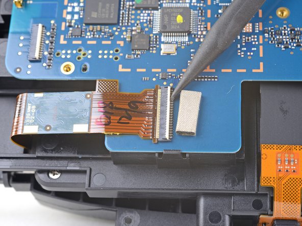
Use tweezers or a spudger to pry up the camera cable cover and remove it.
-
-
-
Este paso está sin traducir. Ayuda a traducirlo
-
Use the flat end of a spudger to pry the camera cable connector straight up from its socket on the motherboard.
-
-
Este paso está sin traducir. Ayuda a traducirlo
-
Use a PH000 driver to remove the five 3.9 mm screws securing the sensor array.
-
-
Este paso está sin traducir. Ayuda a traducirlo
-
Use a PH000 driver to remove the four 3.9 mm screws securing the sensor array.
-
-
Este paso está sin traducir. Ayuda a traducirlo
-
Use a PH000 driver to remove the four 3.9 mm screws securing the sensor array.
-
-
Este paso está sin traducir. Ayuda a traducirlo
-
Lift the sensor array away from the headset to remove it.
-
-
-
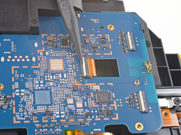
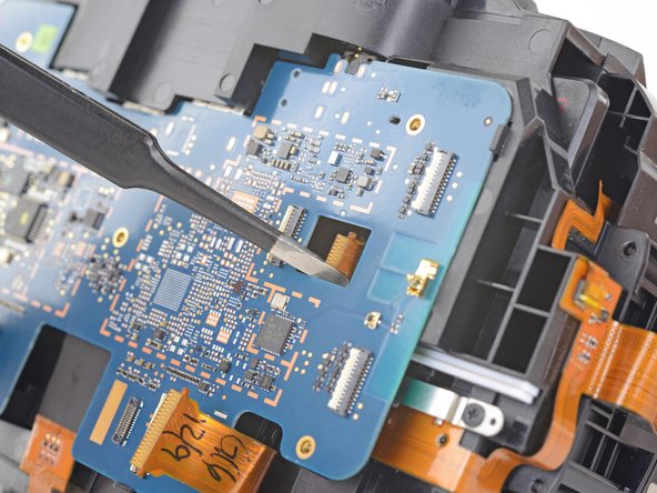
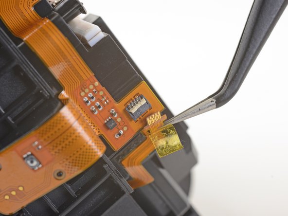
Retira la cinta adhesiva que cubre la toma del cable de interconexión.
-
Utiliza la punta de un spudger para levantar la pequeña tapa de bloqueo de la toma del cable.
-
Desliza el cable de interconexión para sacarlo de su alojamiento en la placa base.
-
-
-
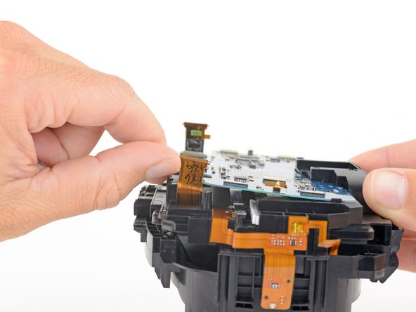
Presiona el extremo no portante de la placa base hacia la parte superior del auricular mientras lo separas del marco central para liberarlo de los clips que aseguran ese extremo.
-
Desliza la placa madre hacia la parte inferior del auricular, por encima de los clips, para retirarla.
-
-
Este paso está sin traducir. Ayuda a traducirlo
-
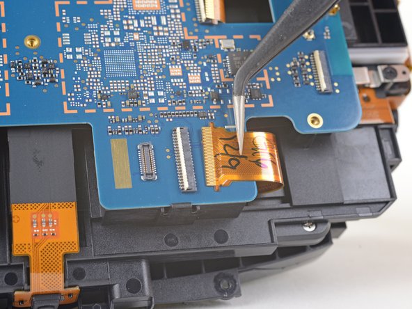
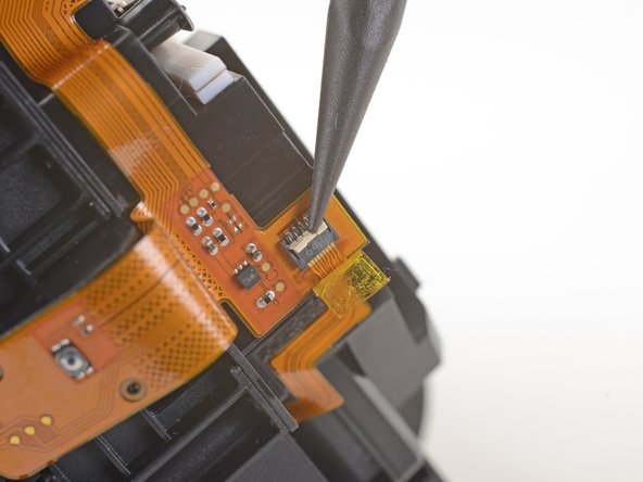
Use a pair of tweezers to peel back the plastic covering the eyepiece midframe cable socket.
-
Use the pointed end of a spudger to flip up the plastic locking flap on the socket.
-
Slide the cable straight out of its socket to remove it.
-
-
Este paso está sin traducir. Ayuda a traducirlo
-
Gently peel the eyepiece midframe cable off of the facerest midframe.
-
-
Este paso está sin traducir. Ayuda a traducirlo
-
Use a PH000 driver to remove the four 3.9 mm screws securing the facerest midframe.
-
-
Este paso está sin traducir. Ayuda a traducirlo
-
Lift the facerest midframe off of the eyepiece midframe.
-
-
Este paso está sin traducir. Ayuda a traducirlo
-
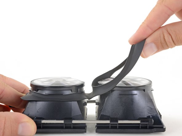
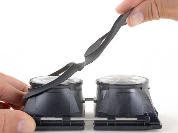
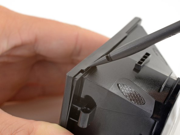
Hinge the OLED and lens frames down and away from the focus knob end of the eyepiece midframe.
-
Once you've rotated the OLED and lens frame about 90 degrees, push them straight down, parallel to the face of the eyepiece midframe, to separate them from the midframe.
-
-
Este paso está sin traducir. Ayuda a traducirlo
-
Gently lift the eyepiece gasket off of the lens and OLED frames to remove it.
-
-
Este paso está sin traducir. Ayuda a traducirlo
-
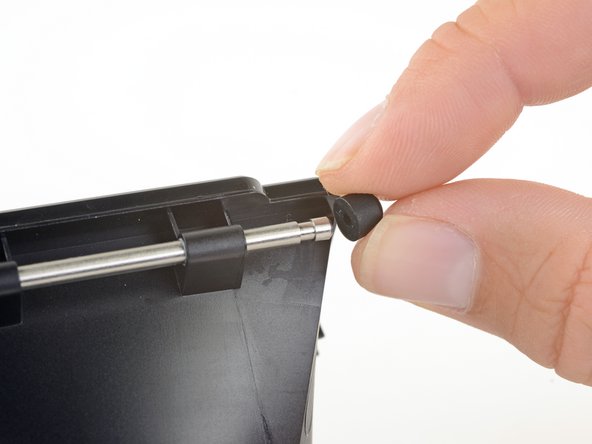
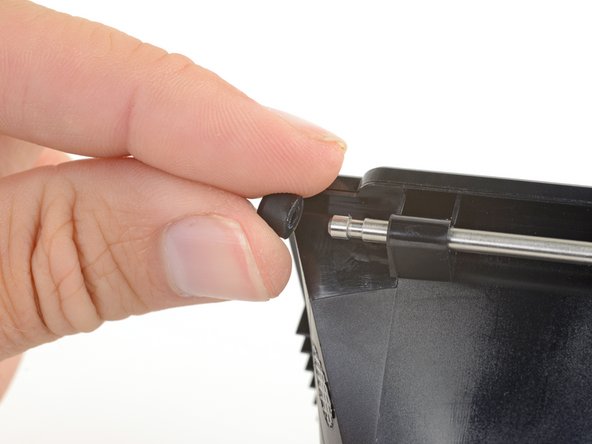
Pull the rubber bumpers off of either end of the support rod.
-
-
Este paso está sin traducir. Ayuda a traducirlo
-
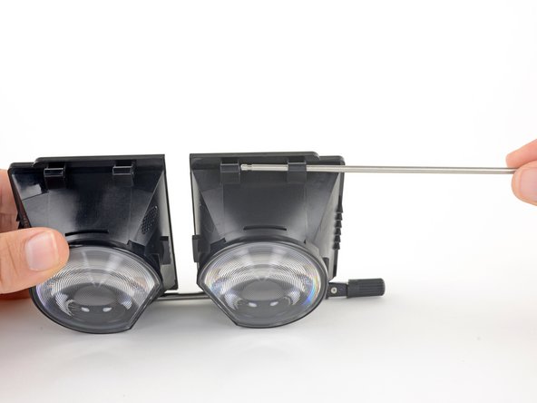
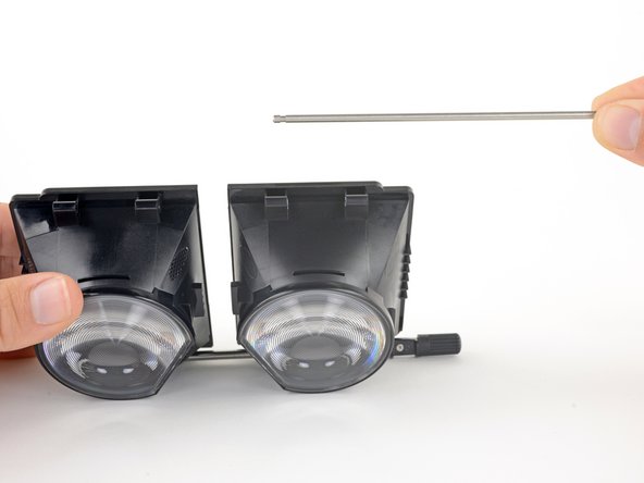
Slide the support rod out of its brackets on the lens and OLED frames.
-
-
Este paso está sin traducir. Ayuda a traducirlo
-
Use a PH000 driver to remove the eight 3.1 mm screws securing the focus rod brackets.
-
-
Este paso está sin traducir. Ayuda a traducirlo
-
Use a PH000 driver to remove the eight 2.4 mm screws securing the OLED covers.
-
-
Este paso está sin traducir. Ayuda a traducirlo
-
Use the flat end of a spudger push up one edge of the OLED cover and start unclipping that edge.
-
-
Este paso está sin traducir. Ayuda a traducirlo
-
Slide the spudger under the clip along that edge to free the rest of the edge.
-
-
Este paso está sin traducir. Ayuda a traducirlo
-
Slide the spudger around the remaining edges of the OLED cover to unclip those edges.
-
-
Este paso está sin traducir. Ayuda a traducirlo
-
Remove the OLED cover.
-
Repeat the last three steps to remove the other OLED cover.
-
-
Este paso está sin traducir. Ayuda a traducirlo
-
Very carefully lift the OLED display by its edges out of its frame.
-
Repeat this process for the other OLED display.
-
-
Este paso está sin traducir. Ayuda a traducirlo
-
Apply an iOpener to the lens to soften the adhesive securing it to the frame.
-
-
Este paso está sin traducir. Ayuda a traducirlo
-
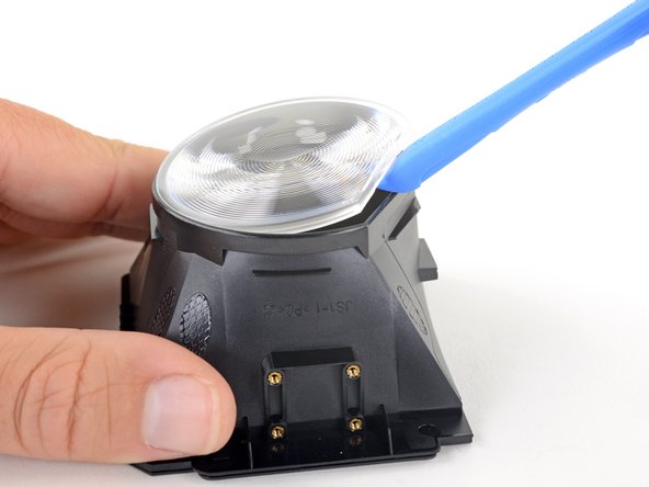
Use an opening tool to pry up the flat edge of the lens.
-
If it's difficult to pry up, apply the iOpener for another 30 seconds to further soften the adhesive.
-
-
Este paso está sin traducir. Ayuda a traducirlo
-
Remove the lens.
-
Repeat the last two steps to remove the other lens.
-
Only the lens and OLED frames remain.
-


Cancelar: No complete esta guía.
2 personas más completaron esta guía.
