Esta versión puede contener ediciones incorrectas. Cambiar a la última instantánea verificada.
Qué necesitas
-
Este paso está sin traducir. Ayuda a traducirlo
-
Insert a SIM eject tool, SIM eject bit, or a paperclip into the small hole on the left edge of the phone, near the top.
-
Press to eject the tray.
-
-
-
Calienta un iOpener y aplícalo en el borde superior de la pantalla durante dos minutos.
-
Toma nota de las siguientes regiones antes de comenzar a hacer palanca:
-
Adhesivo delgado revestido contra el panel de la pantalla
-
Adhesivo grueso
-
El panel de visualización OLED, que es muy propenso a sufrir daños
-
El cable de la pantalla, que puede dañarse al hacer palanca
From my experince, it’s better to use a heat gun (if iFixit sold a good heat gun in volume, they should spruik that). Also, heat ALL sides at the same time BUT concentrate on the top part of the phone where the foam adhesive tape is thickest, second on the bottom where the foam is almost as thick. It also helps to use the 2nd & 3rd images in the series to visualise where the adhesive is.
Ty for the advice I prefer heat gun but my first pixel
-
-
-
Una vez que el borde esté tibio al tacto, aplica una ventosa cerca del borde.
-
Levanta la ventosa e inserta una púa de apertura en el espacio.
-
Si tienes problemas para crear un espacio, vuelve a calentar el borde y vuelve a intentarlo.
From my experience, I had to use a thin blade (such as the ones included with the deluxe iFixit repair kit) to slide into the small gap, and cut away at the foam adhesive. Once enough of a gap is created, the picks can then be used to push the adhesive aside - but the adhesive is so thick, especially -as Brewmaster396 observed in the comments below - at the top right corner behind the screen, that the knife is required to cut it. I failed here - cracking the back layer of my screen - because I didn’t take time to cut all the adhesive away from that thick part, and kept trying to pull the screen off. It doesn’t take a lot of pressure to crack - so maybe it’s more a thing of cutting and floating the screen up, not pulling and prying.
Mark the picks with lines that show how deep you can go in that part of the screen. This will help keep you from accidentally hitting the fragile screen
Matthew Goodwin - Excellent suggestion.
Jon T made a great suggestion about creating a mark on the picks (see above).
Matthew Goodwin responds with an “Excellent suggestion.”
Here we are 8 months later and no lines on the picks in my new pro-tech tool kit, not sure why this hasn’t been implemented at this point in time.
Bob H.
-
-
-
Calienta un iOpener y aplícalo en el borde derecho del teléfono durante dos minutos.
-
Inserta una púa de apertura cerca del borde superior del teléfono, donde ya cortaste el adhesivo.
-
Guía lentamente la púa alrededor de la esquina derecha.
-
Desliza con cuidado la púa por el borde derecho del teléfono para cortar el adhesivo.
-
Repite el paso para el borde izquierdo del teléfono.
-
-
-
Una vez que hayas cortado el perímetro del teléfono, levanta con cuidado el ensamblaje de la pantalla ligeramente por las esquinas derechas.
-
Usa una púa de apertura para cortar cualquier resto de adhesivo.
As long as you’ve disengaged the adhesive relatively evenly around all sides, I found mounting the suction cup in the middle (biased a little to the left or right side), helps a lot on this step.
-
-
-
Usa la punta de un spudger para levantar y desconectar el cable de la pantalla de su conector.
i have to agree with the comment here about the connector. If you press it in the middle, it will bend. Resulting in either bent pins on the motherboard or the display. In my case it was both !
Be careful prying up the connector and apply force only from the side as shown in the picture cause in the longest side there are capacitors that can be broke doing the lever ( happened to me Repair missing capacitor near display connection port )
-
-
-
-
Retira el ensamblaje de la pantalla.
The Parts List does not state you need a replacement display. Is this portion of the Repair Guide copied and pasted from another guide (perhaps the screen replacement guide) or will I need to procure a replacement screen before I attempt to replace the battery?
It is possible to replace the battery without replacing the display, but there is a significant chance you may break the display during removal. It depends on if your display already has micro-fractures, and how stubborn the screen adhesives are. I would personally buy a screen just in case, and return the part if I didn’t need it.
Hello, I recently bought a refurb screen off of eBay to fit. The phone was 100% working before and just needed a new display/battery.
The battery came before the display. I wanted to test the display before doing too much reassembly, so I plugged in the battery, connected the mother/daughter boards with the interconnect cable, and then plugged in the LCD.
When I press the power button there is the usual single buzz from booting, but the display is completely blank.
Is the replacement screen DOA, or are there important traces/connections made by fully assembling the midframe and missing screws before testing the LCD?
If I already have all the ingredients for a fair test of the LCD, then it seems the LCD is bad?
Like I said the phone worked perfectly before… and if the new battery is dead, I would expect no buzz, or at least a battery graphic?
Hi John,
If the phone buzzed, that usually signifies that it has booted up—having no image at that point usually means some kind of display issue. I would suggest disconnecting the display connector, carefully checking for any debris in the socket, and carefully re-connecting it.
I’ve also seen a comment in another Pixel guide that suggests plugging in the display connector before the battery. If that works, please leave a comment!
battery connector is not accessible without removing the display first………. and reassembling, battery has to be connected first, then the plastic piece and then the display
-
-
-
Retira los siguientes tornillos que aseguran el marco medio a la parte posterior:
-
Siete tornillos negros T5 de 4 mm
-
Dos tornillos T5 plateados de 3 mm
-
-
-
Encuentra la pequeña muesca en la esquina inferior izquierda del marco e inserta una púa de apertura.
-
Desliza la púa de apertura a lo largo del borde inferior del teléfono hacia la esquina inferior derecha y déjala allí.
This step was impossible on my phone as a gap could not be formed at the notch to pry the corner up using either pick or playing card . Flathead micro screwdriver was required causing insignificant cosmetic damage at that area.
This step takes a few tries, starting with the pick perpendicular to the phone. Eventually, after gentle prying, it will catch the corner so you can slip the pick underneath. Like everything in this repair, it requires you to be exceedingly delicate and patient.
Take the tip of the tweezers, insert it in the screw hole near where they show to insert the pick and gently pry up. You should be able to move the plate upwards enough to insert the pick
-
-
-
Inserta una púa de apertura separada en el borde derecho del teléfono, cerca de la parte inferior.
-
Empuja lentamente la púa hacia arriba a lo largo de la costura hasta que se suelte el primer clip.
-
Una vez que hayas soltado el clip, deja la púa de apertura en su lugar para evitar que el marco medio se vuelva a sellar.
-
-
Este paso está sin traducir. Ayuda a traducirlo
-
Use the point of a spudger to pry up and disconnect the battery connector.
-
Bend the battery flex cable slightly so that it will not accidentally touch the motherboard.
-
-
Este paso está sin traducir. Ayuda a traducirlo
-
Use the point of a spudger to pry up and disconnect the button strip connector.
-
-
Este paso está sin traducir. Ayuda a traducirlo
-
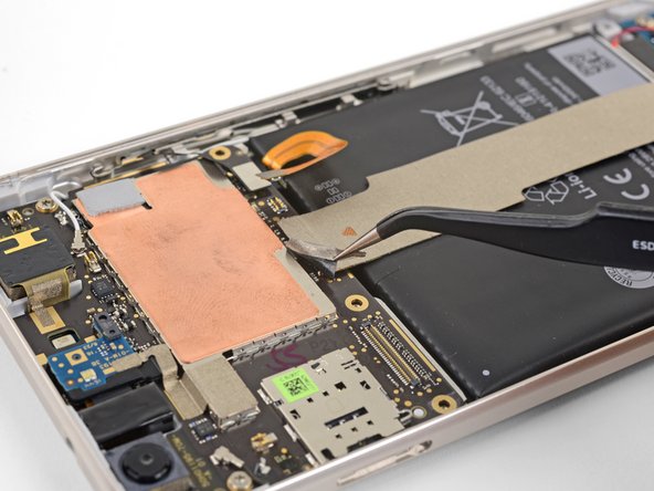
Use tweezers to peel up the tape at the top of the interconnect cable.
-
-
Este paso está sin traducir. Ayuda a traducirlo
-
Use the point of a spudger to pry up and disconnect the interconnect cable from the motherboard.
-
-
Este paso está sin traducir. Ayuda a traducirlo
-
Use the point of a spudger to disconnect the black antenna cable from the motherboard, near the front facing camera module.
-
Route the antenna cable out of its retaining clip.
-
-
Este paso está sin traducir. Ayuda a traducirlo
-
Use the point of a spudger to pry up and disconnect the white antenna cable from the motherboard, near the rear facing camera module.
-
Route the antenna cable out of its retaining clip.
What connector is this? I just broke the connector off the board instead of just disconnecting it. What did I just loose the ability to do?
Update: I pulled the broken connector off the cable, put everything back together, leaving the cable just sandwiched in the right place, and everything seems to be still working completely. Wifi, 4G, Bluetooth.. time will tell what is broken… but it’s not immediately noticeable… I feel really lucky!
David -
Hi jeffersdavid93, did you ever figure out what stopped working with this connector? Thanks!
-
-
Este paso está sin traducir. Ayuda a traducirlo
-
Remove the two 3 mm T5 screws securing the motherboard to the frame.
-
-
Este paso está sin traducir. Ayuda a traducirlo
-
Use the point of a spudger to pry up and loosen the front facing camera module from its socket.
-
-
Este paso está sin traducir. Ayuda a traducirlo
-
Insert the point of a spudger into the headphone jack port and pry upwards to loosen the port from its socket.
-
-
Este paso está sin traducir. Ayuda a traducirlo
-
Use the flat end of a spudger to pry the bottom edge of the motherboard up slightly, loosening it from its recess.
-
-
Este paso está sin traducir. Ayuda a traducirlo
-
Locate the fingerprint sensor cable attached to the underside of the motherboard, near the bottom edge.
-
Use the point of a spudger to pry and release the fingerprint sensor cable from its socket.
-
Peel the cable away from the motherboard.
-
-
Este paso está sin traducir. Ayuda a traducirlo
-
Hold the motherboard by the corners and maneuver it out of its recess, being careful not to snag any cables.
-
Bend the fingerprint sensor cable slightly so that it bows upward near the connector.
-
Stand the motherboard up and position it such that the connector rests against the socket.
-
Use your finger to carefully align the connector and press it into the socket. Do not use excessive force! If done correctly, the socket should hold the connector securely.
-


Cancelar: No complete esta guía.
5 personas más completaron esta guía.


3 comentarios
Thanks for the detailed steps , Question : Where can I buy the replacement motherboard ?
This guide has been updated!