Introducción
Esta guía de reparación fue creada por el personal de iFixit y no ha sido respaldada por Google. Obtén más información sobre nuestras guías de reparación [enlace|Ensuring Quality Repair Information on iFixit|aquí |nueva_ventana=verdadero].
Usa esta guía para quitar o reemplazar la placa base de tu Google Pixel 4 XL.
Precaución: Google advierte que el desmontaje del ensamblaje del láser frontal podría resultar en una exposición peligrosa a emisiones láser infrarrojas invisibles. Lee sus advertencias de seguridad [enlace|https://support.google.com/pixelphone/an...|aquí].
Qué necesitas
-
-
Inserta una herramienta de expulsión de la SIM, una broca o un clip de papel en el pequeño agujero de la bandeja de la tarjeta SIM en el borde izquierdo del teléfono.
-
Presiona firmemente para expulsar la bandeja.
-
Remueve la bandeja de la tarjeta SIM.
-
-
-
Prepara un iOpener y aplícalo en el borde inferior del panel trasero durante un minuto.
-
-
-
Aplica una ventosa al borde caliente del panel trasero presionándolo para crear succión, lo más cerca posible del borde.
-
-
-
Tira hacia arriba de la ventosa con una fuerza fuerte y constante para crear un hueco entre el panel trasero y el marco.
-
Inserta la punta de una púa de apertura en el hueco.
-
-
-
Desliza la púa de apertura por la parte inferior hacia la esquina izquierda para cortar el adhesivo.
-
Con la púa aún insertada, deslízala desde la esquina inferior izquierda hacia la esquina inferior derecha para cortar completamente el adhesivo del lado inferior.
-
Deja la púa insertada en la esquina inferior derecha para evitar que el adhesivo vuelva a sellarse.
-
-
-
Prepara un iOpener y aplícalo en el borde izquierdo durante un minuto.
-
-
-
Prepara el iOpener y aplícalo al borde derecho del teléfono durante un minuto.
-
-
-
Con las dos primeras púas de apertura todavía en su lugar, inserta una tercer púa en la parte inferior del lado derecho.
-
Desliza la púa de la apertura hacia la parte superior del teléfono, cortando el adhesivo del lado derecho.
-
Deténte cuando llegues a la esquina derecha superior y deja la púa insertada.
-
-
-
Desliza la tercera púa de apertura por la esquina superior derecha y por la parte superior del teléfono, cortando la última tira de adhesivo.
-
-
-
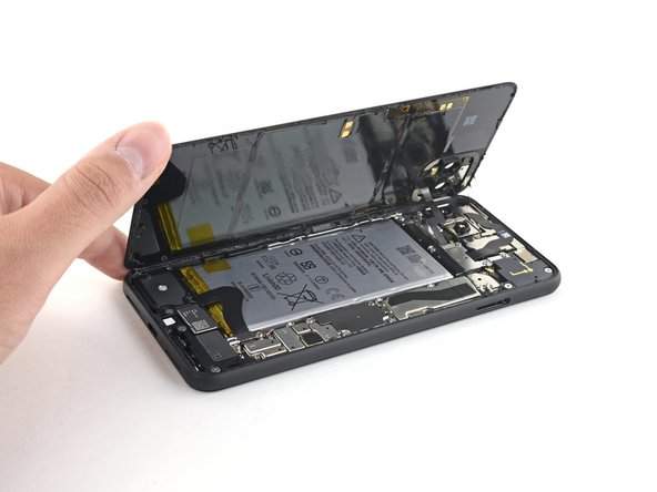
Una vez que hayas cortados alrededor del perímetro del teléfono, levanta con cuidado el borde derecho de la tapa trasera, abriéndolo como un libro.
-
No intentes sacar el panel del todo aun ya que está todavía conectado al teléfono.
-
-
-
Continúa abriendo el panel trasero hasta que puedas apoyarlo en el borde izquierdo del teléfono, teniendo cuidado de no poner ningún tipo de tensión en el cable plano conectado.
Geoff B: These are good instructions. Any technician worth his or her salt will test the device for functionality before sealing it up. That’s why it reads, “During reassembly…and test all functions before sealing it up.” Not confusing if you read and comprehend the full pin.
No instructions on how to fit new sticky gasket before assembly. Removing old adhesive was a messy business, I used IPA on a cotton bud and removed as much as possible with flat end of spudger and kitchen paper.
-
-
-
Remueve los cuatro tornillos Torx T3 que sujetan el escudo del conector de la batería.
-
Un tornillo de 1.8 mm
-
Un tornillo de 4.1 mm
-
Un tornillo de hombro de 4.4 mm
-
Un tornillo de hombro de 4.0 mm
Anyone know the thread size of the 1.8mm screw mentioned here? Mine went missing, and I need to get a replacement. I've got a bunch of tiny screw kits, but none of them have fit!
-
-
-
-
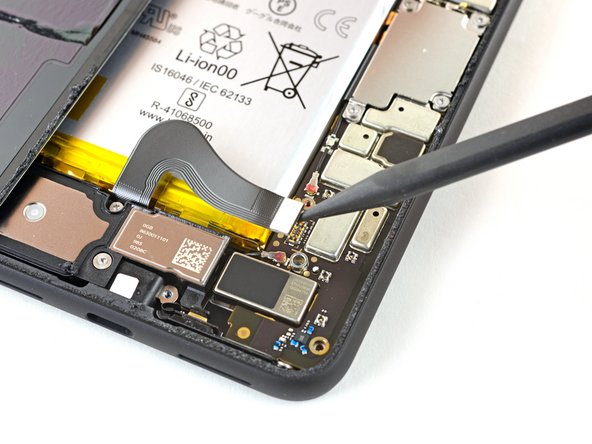
Usando el extremo puntiagudo de un spudger, haz palanca en el conector de la batería directamente desde la placa madre para desconectar la batería.
What are the 5 copper dots under the battery connector for.
When you reattach the connector to the motherboard this is a good time to power up and check basic functionality temporarily. Even though it had appeared it was correctly lined, my camera was not functional, in particular the switch button from the rear to the front camera, I was stuck in selfie mode. Then I was getting a message on the screen, possible hardware or software issues. Once I reattached the connecter (several times) until it was correctly inlined, the error went away and I was able to switch from the rear and front cameras.
That was a good call! Thanks!
Esther -
-
-
-
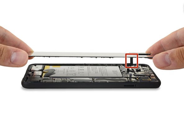
Usa un destornillador T3 Torx para remover los dos tornillos de 4.1 mm que sujetan el panel trasero de la tapa del conector.
Wouldn’t it make more sense to use the same (orange) color circles as the other 4.1mm screw?
Maybe Google did it to avoid exchange in the models where they differ
-
-
-
Utiliza el extremo puntiagudo de un spudger para levantar y desconectar el conector del panel trasero.
-
-
-
Remueve el panel trasero.
REASSEMBLY ADHESIVE: This is the step during reassembly that you'll want to set the back glass adhesive strip on (before you reattach ribbons). Set the adhesive strip into the body of the phone with the red tabs down (toward the body of the phone, it will simply rest inside the lip of the phone body). Press the back glass onto the adhesive strip to set the strip onto the back glass, lift the back glass back out of the body of the phone. Next reattach the ribbons, test functions, reattach connector covers, peel red adhesive cover off of the adhesive (on the back glass) then set the back glass into the phone lip. This could have been explained far better but was skipped over and the generic adhesive instructions posted in the comments are useless for this.
There are also detailed instructions at answer 742532, "How do I apply new back panel adhesive on a Pixel 4xl?" (sorry it doesn't let me link directly). But it advises adhering the adhesive to the main frame first before the glass. I do notice a slight lip on the main frame on both sides, which seems less forgiving to align with than the glass, so I would imagine doing the frame first would be easier? I haven't done this yet myself, so would be interested in opinions.
Update: it appears the discrepancy is due to a difference between the third-party adhesives and the iFixit "genuine" one. The iFixit one is not mirror symmetric and must be adhered to the glass back first, though it has cutouts that avoid protrusions and facilitate this. The third-party one (I believe) has no such cutouts and thus must go on the frame first.
However, in trying to follow Michael's instructions, I could not get the adhesive and red tabs off the blue plastic without distorting the adhesive, and had to take the clear side off first. I ended up directly placing the adhesive onto the glass back, without the frame to help align (I posted my method in the above-mentioned answer 742532). The cutouts in the blue plastic seem to have been made with this in mind.
-
-
-
Suavemente, empuja la lengüeta del adhesivo de la batería para permitir un acceso más fácil a los tornillos que están debajo de ella.
-
-
-
Usando el extremo puntiagudo de un spudger, saca la cámara y los conectores del sensor directamente de la placa madre.
-
-
-
Remueve los tres tornillos T3 Torx que sujetan el ensamblaje del sensor y de la cámara frontal:
-
Dos tornillos de 2.7 mm
-
Un tornillo de 3.1 mm
-
-
-
Usa un par de pinzas para remover el ensamblaje de sensor y cámara frontal.
Additional Sensor from Step 28 is held down with adhesive. Gently pry up on cable to remove sensor assembly.
-
-
-
Utiliza un destornillador Torx T3 para quitar los cuatro tornillos de 3,5 mm que sujetan la cubierta del conector de la pantalla.
-
-
-
Usa un par de pinzas para quitar la cubierta del conector de la pantalla.
-
-
-
Usa el extremo plano de un spudger para desconectar el conector de la pantalla de la placa base.
-
-
-
Utiliza un destornillador Torx T3 para quitar el tornillo de 2,7 mm que sujeta la placa base al marco.
-
-
-
Usa el extremo puntiagudo de un spudger para desconectar el conector de los botones laterales de la placa base.
-
Desconecta los dos conectores de la cámara trasera de la placa base.
The screw on the top left of the motherboard is out in this picture, but removal is not included in previous steps. It’s still visible in Step 30.
Thank you! Good catch. I’ve added a new step for removing that screw.
-
-
-
Usa el extremo puntiagudo de un spudger y levanta suavemente para soltar el conector de antena superior de la placa base.
-
Desconecta el conector de la antena inferior.
-
-
-
Con un spudger, gira el extremo superior de la placa base hacia arriba y fuera del marco del teléfono.
-
-
-
Levanta lentamente la placa base, teniendo cuidado de no enganchar ningún conector del cable plano.
-
Retira completamente la placa base.
-


Compara la nueva pieza de repuesto con la original, es posible que tengas que transferir los componentes restantes o retirar los respaldos adhesivos de la nueva pieza antes de instalarla.
Para volver a montar el dispositivo, sigue los pasos anteriores en orden inverso.
Lleva tus desechos electrónicos a un centro de reciclaje certificado.
¿La reparación no salió según lo planeado? Prueba algunas solución de problemas básicos o pide ayuda a nuestra [enlace|https://www.ifixit.com/Answers/Device/Go...|Comunidad de respuestas].
Cancelar: No complete esta guía.
10 personas más completaron esta guía.
Un agradecimiento especial a estos traductores:
100%

¡ Francisco Javier Saiz Esteban nos está ayudando a reparar el mundo! ¿Quieres contribuir?
Empezar a traducir ›


4 comentarios
where can i purchase a pixel 4xl motherboard replcement?
This guide doesnt mention thatthe front camera and sensor array is married to the motherboard and replacing one without the other will cause face unlock to not function. This situation throws a "Certificate Expired" error and neither factory reset nor reflashing/sideloading firmware corrects this. Google support says repair or replace is the only remedy. I'm currently trying to prove that assertion wrong.
Hey J L, Did you ever manage to find a solution for the certificate expired issue? I recently replaced my front camera and sensor assembly hoping to fix broken face unlock sensor. Encountering the same certificate expired issue after replacement
Echo -